
Color-filter-based multi-channel fiber bragg grating demodulator

A fiber grating demodulation and color filter technology, which is applied in the field of fiber grating wavelength demodulation instruments and fiber grating demodulators, can solve the problems of slow demodulation speed, high cost of demodulators, and large volume of spectrometers. Low, simple structure effect

Active Publication Date: 2013-06-12
HEILONGJIANG UNIV
View PDF7 Cites 3 Cited by
  • Summary
  • Abstract
  • Description
  • Claims
  • Application Information

AI Technical Summary

Problems solved by technology

[0004] In order to solve the problems of large volume of spectrometer, high cost of demodulator and slow demodulation speed in the existing demodulation mode of fiber grating sensor, the present invention proposes a multi-channel fiber grating demodulator based on color filters

Method used


Image

  • Color-filter-based multi-channel fiber bragg grating demodulator
  • Color-filter-based multi-channel fiber bragg grating demodulator
  • Color-filter-based multi-channel fiber bragg grating demodulator

Examples


specific Embodiment approach 1

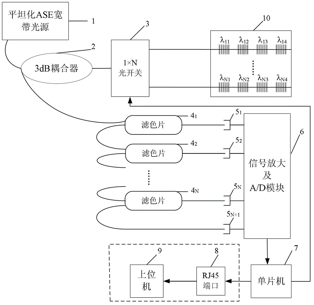
[0024] Specific implementation mode one: refer to figure 1 This embodiment will be specifically described. The color filter-based multi-channel fiber grating demodulator described in this embodiment includes: a flattened ASE broadband light source 1, a 3dB coupler 2, a 1×N optical switch 3, and N color filters 4 1 to 4 N , N+1 PIN photodetectors 5 1 to 5 N+1 , signal amplification and A / D conversion module 6, single-chip microcomputer 7 and N-way sensing fiber grating 10;

[0025] An optical signal input and output end of the 3dB coupler 2 is simultaneously connected to the optical signal output end of the flattened ASE broadband light source 1 and the first color filter 4 1 The optical signal input terminal of the 3dB coupler 2 is connected to an optical signal input and output terminal of the 1×N optical switch 3, and the N fiber grating signal input and output terminals of the 1×N optical switch 3 are respectively connected to The N-way fiber grating signal input and o...

specific Embodiment approach 2

[0028] Specific embodiment two: This embodiment is to further illustrate the multi-channel fiber grating demodulator based on color filters described in specific embodiment one. In this embodiment, the flattened ASE broadband light source 1 is amplified spontaneous radiation The light source emits an optical signal with a wavelength of 1525nm to 1565nm and a light intensity of 20mw to 200mw.

specific Embodiment approach 3

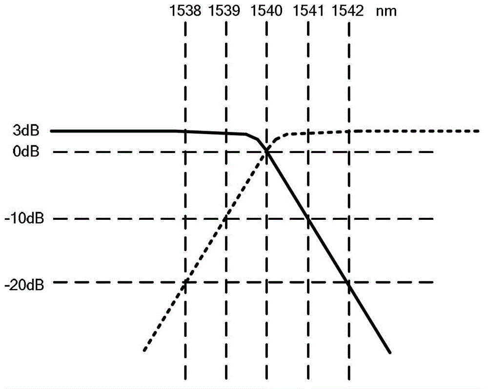
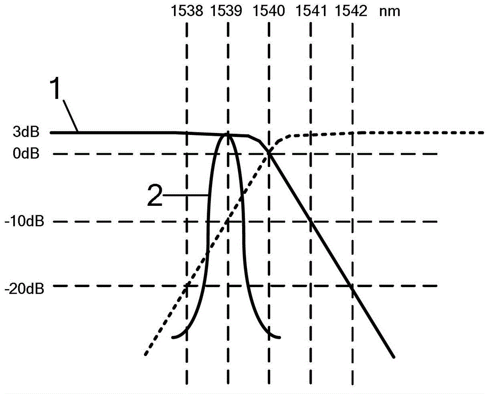
[0029] Specific embodiment three: This embodiment is to further illustrate the multi-channel fiber grating demodulator based on color filters described in specific embodiment one. In this embodiment, N color filters 4 1 to 4 N The reflection / transmission transition bandwidth is 2nm, the corresponding light intensity attenuation is 20dB, N color filters 4 1 to 4 N The corresponding center wavelengths of the color filters are not the same, and the corresponding center wavelength difference between every two connected color filters is 2nm.


PUM

PropertyMeasurementUnit
Wavelengthaaaaaaaaaa
Light intensityaaaaaaaaaa
Center wavelengthaaaaaaaaaa

Abstract

The invention discloses a color-filter-based multi-channel fiber bragg grating demodulator, relates to the technical field of fiber bragg grating wavelength demodulation, and aims to solve the problems of large spectrometer size, high demodulator cost and low demodulation speed under the conventional demodulation mode for a fiber bragg grating sensor. The color-filter-based multi-channel fiber bragg grating demodulator is low in cost and simple in structure. Wavelengths of optical signals are compared by N continuous wavelength color filters, the wavelength of the optical signal is quickly determined, and the optical signal is input into a single-chip through a positive intrinsic negative (PIN) photoelectric detector and a signal amplification and analogue / digital (A / D) conversion module, and the demodulation frequency can reach 500kHz, so that the signal is quickly and accurately processed and demodulated. The color-filter-based multi-channel fiber bragg grating demodulator can be applied to the technical fields of temperature, stress and displacement detection and monitoring in industrial production.

Description

technical field [0001] The invention relates to an optical fiber grating demodulator, in particular to an optical fiber grating wavelength demodulator using a color filter to split light and a photoelectric detection array to collect. It belongs to the technical field of optical fiber grating wavelength demodulation. Background technique [0002] In many special occasions, fiber grating sensors have many characteristics that traditional sensors do not have. As a sensor with an intelligent structure, fiber grating has the advantages of small size, light weight, corrosion resistance, strong anti-electromagnetic interference ability, easy integration, and simple structure. Physical quantities such as strain, flow velocity, flow rate, and viscosity are detected. [0003] The core work of the demodulation of the fiber grating sensing signal is to read and transform the return values ​​of different center wavelengths of the fiber grating, and then obtain the change of external i...

Claims


Application Information

Patent Timeline
IPC IPC(8): G01D5/38G01D5/353G02F2/00
Inventor 吕国辉商绍华
Owner HEILONGJIANG UNIV
Learn More