Plume heat effect impact analysis method used for 10N thruster in communication satellite and based on standard template library (STL)

An impact analysis and communication satellite technology, applied in the field of satellite design, can solve the problems affecting the overall thermal effect calculation, inconsistency, etc., to achieve the effect of small particle size and simple area calculation

Active Publication Date: 2013-06-12
CHINA ACADEMY OF SPACE TECHNOLOGY
View PDF8 Cites 5 Cited by
  • Summary
  • Abstract
  • Description
  • Claims
  • Application Information

AI Technical Summary

Problems solved by technology
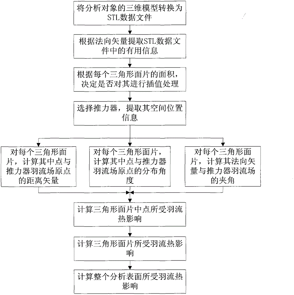
Without vector information, it is impossible to judge the plume thermal influence on the upper surface or the lower surface (or inner surface or outer surface) of the analysis object by the program;
[0006] (3) When this method analyzes the parabolic antenna, the area element used is the surface trapezoid. Since the surface trapezoid is radially distributed along the apex of the paraboloid, the area of ​​the trapezoid far away

Method used


Image

  • Plume heat effect impact analysis method used for 10N thruster in communication satellite and based on standard template library (STL)
  • Plume heat effect impact analysis method used for 10N thruster in communication satellite and based on standard template library (STL)
  • Plume heat effect impact analysis method used for 10N thruster in communication satellite and based on standard template library (STL)

Examples


Embodiment 1

[0073] The analysis object adopted in this embodiment is a device that does not need grid interpolation. Set the 3D model of the shaped reflector of the communication antenna and the model after STL meshing see Figure 5 and Figure 6 shown. Figure 7 A schematic diagram of the analysis results. The result of thermal effect analysis is: the maximum heat flux density is: 1.2421kW / m 2 ; The maximum heat flux area is surrounded by Point1 (X-18.5mm, 1470.5mm, 4420.5mm), Point2 (X-12.7mm, 1473.8mm, 4423.0mm), and Point3 (X-10.8mm, 1463.9mm, 4416.9mm) The area is 37.6mm 2 The triangular area; the heat capacity of the entire reflective surface affected by the plume is 174.8W.

[0074] If the method in Chinese patent CN201010606039 is adopted, the established model is a standard paraboloid, and the maximum heat flux obtained by analysis is 1.1658kW / m 2 .

[0075] From the three-dimensional model of the antenna reflector, it can be seen that the place with the maximum heat flux ...

Embodiment 2

[0077] The analysis object adopted in this embodiment is a device requiring grid interpolation.

[0078] Figure 8 The resulting STL mesh for the raw 3D model of the solar wing. It can be seen that although the solar wing has a large surface area, due to its single normal vector, only Figure 8 The 6 triangle meshes shown completely represent the surfaces of the 3 solar wings. Such sparse data cannot be used to analyze the thermal effects of the plume.

[0079] Figure 9 is the grid obtained after 6 iterations using the interpolation method in the present invention. To get a smaller mesh, continue to Figure 9 Iterating over the grid shown, we get Figure 10 grid shown. Figure 11 for right Figure 10 The results of a thermal impact analysis of the mesh plume are shown.

[0080] Table 1 is based on Figure 8 The curved surface shown is the object, and the analysis results are compared by the method of the present invention and the method in Chinese patent CN201010606...


PUM


Abstract

The invention relates to a plume heat effect impact analysis method used for a 10N thruster in a communication satellite and based on a standard template library (STL), and belongs to the technical field of satellite design. According to the method, not only can a plume heat effect on a device with a regular shape be analyzed, but also the plume heat effect on a device with an irregular shape can be analyzed, specific surfaces of a researched target can be judged, and area of each area infinitesimal can be accurately calculated and obtained. According to the plume heat effect impact analysis method used for the 10N thruster in the communication satellite and based on the STL, a three-dimensional model is only required to be provided, the plume heat effect on the surfaces can be analyzed, area calculation is simple, a deviation between the area sum of triangle grids and a practical area of the researched target is small, and an analysis result is closer to a practical condition.

Description

technical field [0001] The invention relates to an STL-based method for analyzing the thermal effect of a 10N thruster plume on a communication satellite, and belongs to the technical field of satellite design. Background technique [0002] The satellite thruster plume will affect the performance and life of the satellite. At present, the influence of the satellite thruster plume is mainly concentrated on the analysis of the influence of disturbance force and the influence of thermal effect. The analysis methods include theoretical calculation and fitting of test data. [0003] In the layout process of communication satellites, the influence of jet plumes of bicomponent thrusters on satellite surface equipment should be considered. In engineering practice, the data fitting method based on test data has been used to analyze the thermal and dynamic effects caused by the impact of the two-component thruster, such as the name disclosed in Chinese patent CN201010606039, which is...

Claims


Application Information

Patent Timeline
IPC IPC(8): G01M9/00
Inventor 徐春生李洋夏永泉曹鹏
Owner CHINA ACADEMY OF SPACE TECHNOLOGY
Why Eureka
Try Eureka