Test device and method for forming high-speed stable flow field

A technology for stabilizing the flow field and test device, which is used in fluid dynamics test, measuring device, testing of machine/structural components, etc. It can solve the problems of cavitation, high turbulence, and difficulty in ensuring the quality of the flow field.

Active Publication Date: 2013-06-12
中国船舶重工集团公司第七〇二研究所
View PDF6 Cites 24 Cited by
  • Summary
  • Abstract
  • Description
  • Claims
  • Application Information

AI Technical Summary

Problems solved by technology

[0003] Water tunnels and water tanks are commonly used hydrodynamic test equipment. Both of them use impeller pumps to drive water flow. The water tunnels are used for testing the fluid characteristics of the test section without free surfaces, and can be used for conventional hydrodynamic tests. , cavitation test, boundary layer mechanism and water noise test, etc. Most of the existing water tunnels use the impeller pump as the power to drive the water flow, through the stabilization section, contraction section, test section, diffuser section and return pipeline to the impeller pump, A closed circulation water tunnel is formed, which can reach a certain water flow velocity, but because the flow establishment method is driven by the impeller pump, it is easy to cause cavitation of the impeller pump blades due to the reduction of the cavitation number under high-speed flow conditions. This results in a stall with high turbulence
Therefore, it is difficult for conventional water tunnels to achieve high flow rates, and it is not suitable for the study of high-speed flows accompanied by cavitation.
On the other hand, conventional closed-circulation water tunnels still have serious air bubble backflow, which makes it difficult to ensure a good flow field quality

Method used


Image

  • Test device and method for forming high-speed stable flow field

Examples


Embodiment Construction

[0030] The specific implementation manner of the present invention will be described below in conjunction with the accompanying drawings.

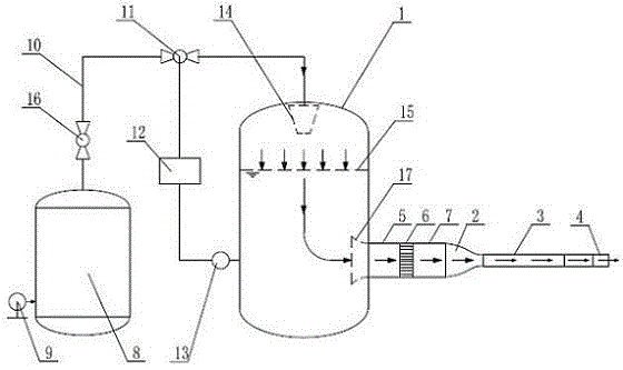
[0031] See figure 1 , the test device for forming a high-speed stable flow field of the present invention includes a water tank 1, an inlet is provided on the top of the water tank 1, an outlet is provided on the side wall of the water tank 1, and a horizontal flow channel is connected to the outlet through a pipeline, and the horizontal flow channel includes a sequence The connected drainage section 17, stable section, contraction section 2, test section 3 and expansion section 4, the expansion section 4 has an outlet gate, and the stable section includes the first steady flow section 5, the honeycomb section 6 and the second steady flow section 7 , the drainage section 17 adopts an arc-shaped bell mouth shape, so that the water flows out smoothly; the length of the stable section is greater than 3 times the equivalent diameter of its cro...


PUM


Abstract

The invention provides a test device for forming a high-speed stable flow field. The test device comprises a water tank, wherein an outlet is formed at the side wall of the water tank; the outlet is connected with a horizontal flow channel through a pipeline; the horizontal flow channel comprises a drainage section, a stabilizing section, a contraction section, a test section and an expansion section; the water tank is connected with an air supply system and a pressure control system through a pipeline, wherein the air supply system comprises an air source pressure tank and an air compressor, the air source pressure tank is connected with the water tank through an air inlet pipeline, and a flow control valve is formed on the air inlet pipeline; and the pressure control system comprises the flow control valve, a PLC (programmable logic controller), a pressure transmitter and the water tank, and the pressure transmitter is arranged on an outlet axis of the water tank. A method for forming the high-speed stable flow field comprises the following steps of: driving the flow through high-pressure air, and controlling the high-pressure air by the pressure control system, namely controlling the pressure of an inlet of the horizontal flow channel to be stable, so as to obtain the stable flow velocity at the test section. Through the device and the method, a high-speed and stable test flow field with excellent flow field quality can be formed.

Description

technical field [0001] The invention relates to the technical field of hydrodynamic tests, in particular to a test device and method for driving water flow through controllable high-pressure gas to form a high-speed stable flow field. Background technique [0002] Hydrodynamic test is to use various experimental equipment and instruments to measure various physical parameters that characterize the flow of water or other liquids and their interaction with solid boundaries, and analyze and process data to study the relationship between various parameters. The hydrodynamic experiment has a wide range of contents and a wide variety of test equipment. With the development of science and technology and the improvement of research level, the focus of hydrodynamic research has begun to shift to high-speed flow, such as high-speed ships, high-speed underwater weapons, high-speed fluid machinery, high-speed jets, etc. The research on these high-speed flows also requires the help of c...

Claims


Application Information

Patent Timeline
Patent Type & Authority Applications(China)
IPC IPC(8): G01M10/00
Inventor 陈伟政王宝寿宋志平颜开张志刚
Owner 中国船舶重工集团公司第七〇二研究所
Why Eureka
Try Eureka