Resistance device based on magneto-rheological cement and magnetic control rheostat

A technology of magnetorheological cement and resistance device, which is applied in the field of adjustable rheostat and adjustable magnetron rheostat based on magnetorheological materials, can solve the problems of limiting the application of magnetorheological fluid engineering, poor settlement stability, etc., and achieves a simple structure. , rapid reaction, good reversibility

Active Publication Date: 2013-06-12
CHONGQING UNIV
View PDF1 Cites 18 Cited by
  • Summary
  • Abstract
  • Description
  • Claims
  • Application Information

AI Technical Summary

Problems solved by technology

However, magnetorheological fluids have the characteristics of poor sedimentation stability, which limits the further engineering application of magnetorheological fluids.
[0003] Researchers at home and abroad have overcome the problem of poor sedimentation stability by developing a high-viscosity polymer matrix to replace the liquid matrix of magnetorheological fluid, and then a new magnetorheological material - magnetorheological fluid has been born. Cement and magnet...

Method used


Image

  • Resistance device based on magneto-rheological cement and magnetic control rheostat
  • Resistance device based on magneto-rheological cement and magnetic control rheostat
  • Resistance device based on magneto-rheological cement and magnetic control rheostat

Examples


Embodiment Construction

[0017] In order to make the purpose of the present invention, technical solutions and advantages clearer, the present invention will be described in further detail below in conjunction with accompanying drawing:

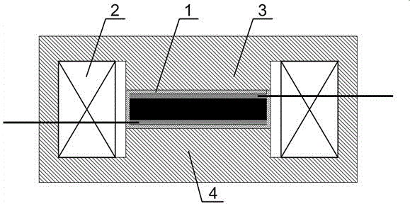
[0018] The magnetron rheostat of magnetorheological clay is composed of magnetorheological clay resistance device and electromagnetic generating device.

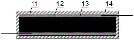
[0019] figure 2 A schematic structural diagram of a magneto-rheological glue resistance device is shown, which includes a closed insulating casing 11 , electrodes 12 , magnetorheological glue 13 and terminals 14 . The closed insulating jacket 11 is in the shape of a cuboid, enclosing the magnetorheological cement in the working position, and the magnetorheological cement 13 is under the action of an external magnetic field. Changes, from the initial free distribution to gradually form a chain structure distribution, due to the change of the arrangement structure, the distance between the soft magnetic particles i...


PUM


Abstract

The invention discloses a resistance device based on magneto-rheological cement and a magnetic control rheostat. The resistance device based on the magneto-rheological cement comprises an insulating sleeve, electrodes, magneto-rheological cement and wiring ends, wherein the magneto-rheological cement is fixed inside the insulating sleeve; the electrodes are distributed on the upper inner surface and the lower inner surface of the insulating sleeve, and are in sufficient contact with the magneto-rheological cement; and the wiring ends are welded on the two electrodes. The magnetic control rheostat comprises excitation coils, an upper magnetic pole, a lower magnetic pole and the resistance device based on the magneto-rheological cement, wherein the resistance device based on the magneto-rheological cement is fixed between the upper magnetic pole and the lower magnetic pole; the excitation coils are coiled between the upper magnetic pole and the lower magnetic pole; the excitation coils, the upper magnetic pole, the lower magnetic pole and the resistance device based on the magneto-rheological cement commonly form a closed bidirectional magnetic loop; and the intensity of a magnetic field of the closed magnetic loop is adjusted by controlling the magnitude of the current of the excitation coil, so that the resistance of the resistance device based on the magneto-rheological cement can be changed. The invention designs the rheostat for controlling the resistance value of the device by a magnetic field generated by the current through using the characteristic that the conduction property of the magneto-rheological cement can be enhanced by additionally arranging the magneto-rheological cement with the increase of magnetic fields. The magnetic control rheostat is applicable to an electronic control system or a computer control system.

Description

technical field [0001] The invention belongs to the technical field of magnetorheological materials and applications, and relates to an adjustable rheostat, in particular to an adjustable magnetron rheostat based on magnetorheological materials. Background technique [0002] Magnetorheological materials are smart materials that can be affected by an external magnetic field and change their specific properties. Among them, the most representative magnetorheological material, magnetorheological fluid, has been successfully applied in engineering practice. However, magnetorheological fluids have the characteristics of poor sedimentation stability, which limits the further engineering application of magnetorheological fluids. [0003] Researchers at home and abroad have overcome the problem of poor sedimentation stability by developing a high-viscosity polymer matrix to replace the liquid matrix of magnetorheological fluid, and then a new magnetorheological material - magnetorhe...

Claims


Application Information

Patent Timeline
IPC IPC(8): H01C10/14
Inventor 余淼居本祥浮洁
Owner CHONGQING UNIV
Why Eureka
Try Eureka