Switch power supply

A switching power supply, switching tube technology, applied in electrical components, output power conversion devices, conversion equipment with intermediate conversion to AC, etc. Improved performance and lower blocking voltage

Inactive Publication Date: 2013-06-12
SHANGHAI STEP ELECTRIC +1
View PDF10 Cites 7 Cited by
  • Summary
  • Abstract
  • Description
  • Claims
  • Application Information

AI Technical Summary

Problems solved by technology

This method uses more devices, higher cost and poor reliability.

Method used


Image

  • Switch power supply

Examples


Embodiment Construction

[0015] The present invention will be further described below in conjunction with the accompanying drawings.

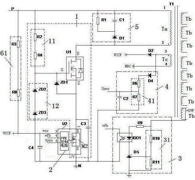
[0016] Such as figure 1 As shown, the switching power supply according to an embodiment of the present invention includes a power conversion circuit 1, a PWM control circuit 2, a transformer T1, an output detection feedback circuit 3, a voltage detection circuit 4, an RCD absorption circuit 5 and a power supply circuit.

[0017] The transformer T1 comprises a primary winding Ta and at least one secondary winding Tb. One end of the primary winding Ta is coupled to the positive pole of the DC power input end. The secondary winding Tb is coupled with a load. An RCD snubber circuit 5 is connected in parallel to this primary winding Ta. The RCD absorption circuit 5 is composed of a resistor R1, a capacitor C1 and a diode D1.

[0018] The power conversion circuit 1 includes a first switching tube U1 , a second switching tube M2 and a switching tube driving circuit. The ...


PUM


Abstract

The invention relates to a switch power supply, which comprises a power converting circuit, a PWM (pulse-width modulation) control circuit and a transformer, wherein one end of a primary winding of the transformer is coupled with a positive electrode of the input end of a direct current power supply, the power converting circuit comprises a first switch tube, a second switch tube and a switch tube driving circuit, the switch tube driving circuit comprises a current limiting circuit, a first clamping circuit and a second clamping circuit, two ends of the current limiting circuit are respectively coupled with the positive electrode of the input end of the direct current power supply and is coupled with one end of the first clamping circuit, the other end of the first clamping circuit is coupled with a source electrode of the second switch tube, the second clamping circuit comprises a second diode, a positive electrode and a negative electrode of the second diode are respectively coupled with a source electrode and a grid electrode of the first switch tube, the grid electrode of the first switch tube is coupled with a public joint of the current limiting circuit and the first clamping circuit, a drain electrode of the first switch tube is coupled with the other end of the primary winding, and the source electrode of the first switch tube is coupled with a drain electrode of the second switch tube. A grid electrode of the second switch tube is coupled with the output end of the PWM control circuit, and the source electrode of the second switch tube is grounded. Two switch tubes are adopted for series connection, so the switch power supply can normally work under the wide input voltage condition.

Description

technical field [0001] The invention relates to a switching power supply, in particular to a switching power supply for a frequency converter. Background technique [0002] The switching power supply in the inverter needs to provide multiple output power supplies such as IGBT drive power, main control chip power, and communication power. In order to make the switching power supply smaller, a flyback switching power supply is generally used. However, due to the existence of the flyback voltage, the common flyback switching power supply, the switching tube bears the voltage stress exceeding the bus voltage, and cannot work reliably at a higher voltage. At present, in inverters with a DC bus voltage of 200V to 1400V, there are mainly two ways to realize the normal operation of the switching power supply: [0003] 1. The method of using a power frequency transformer: the input voltage 380VAC or 690VAC is changed to 220VAC through a power frequency transformer, and then the inpu...

Claims


Application Information

Patent Timeline
Patent Type & Authority Applications(China)
IPC IPC(8): H02M3/28H02M1/08
Inventor 陈雷江振洲邢辉庞忠浩张辉
Owner SHANGHAI STEP ELECTRIC
Why Eureka
Try Eureka