
Dual-threshold control system and method for switch power supply

A switching power supply and control system technology, applied in control/regulation systems, electrical components, and adjustment of electrical variables, can solve problems such as poor dynamic response speed, large output voltage fluctuations, and long cut-off time of the switch tube Q1, and achieve Improve the dynamic response speed and reduce the effect of output voltage ripple

Inactive Publication Date: 2013-06-12
SHENZHEN FM ELECTRONICS GRP CO LTD
View PDF4 Cites 20 Cited by
  • Summary
  • Abstract
  • Description
  • Claims
  • Application Information

AI Technical Summary

Problems solved by technology

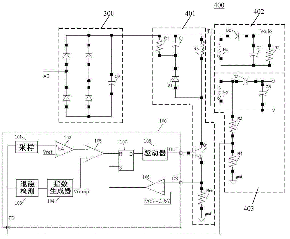
When the output load of the system is large, the time for the current flowing through the diode D2 to drop from the peak value to zero is short, resulting in a short time for the demagnetization of the transformer T1, so that the time for the switch tube Q1 to be kept off is also short
Conversely, when the output load of the system is small, the time for the current flowing through the diode D2 to drop from the peak value to zero is longer, resulting in a longer time for the demagnetization of the transformer T1, and a longer time for the switch tube Q1 to be kept off
[0008] Therefore, when the output load of the above-mentioned switching power converter circuit changes suddenly from light load to heavy load, since the switching tube Q1 remains off for a long time at light load, when the system suddenly changes, the demagnetization detection circuit has not yet When the time when the current of diode D2 crosses zero is detected in time, when the system turns on the switch tube Q1 in time in the future, the output voltage of the system has already dropped significantly, resulting in unstable output voltage of the system, and the dynamic response speed of the system to load changes is poor.
And because the energy received by the secondary coil of the transformer is the same when the system is under light load and heavy load, when the system suddenly changes from light load to heavy load, the output voltage fluctuates greatly, at least the system output voltage ripple is also large

Method used


Image

  • Dual-threshold control system and method for switch power supply
  • Dual-threshold control system and method for switch power supply

Examples


Embodiment Construction

[0024] Below, the present invention will be described in detail with reference to the accompanying drawings.

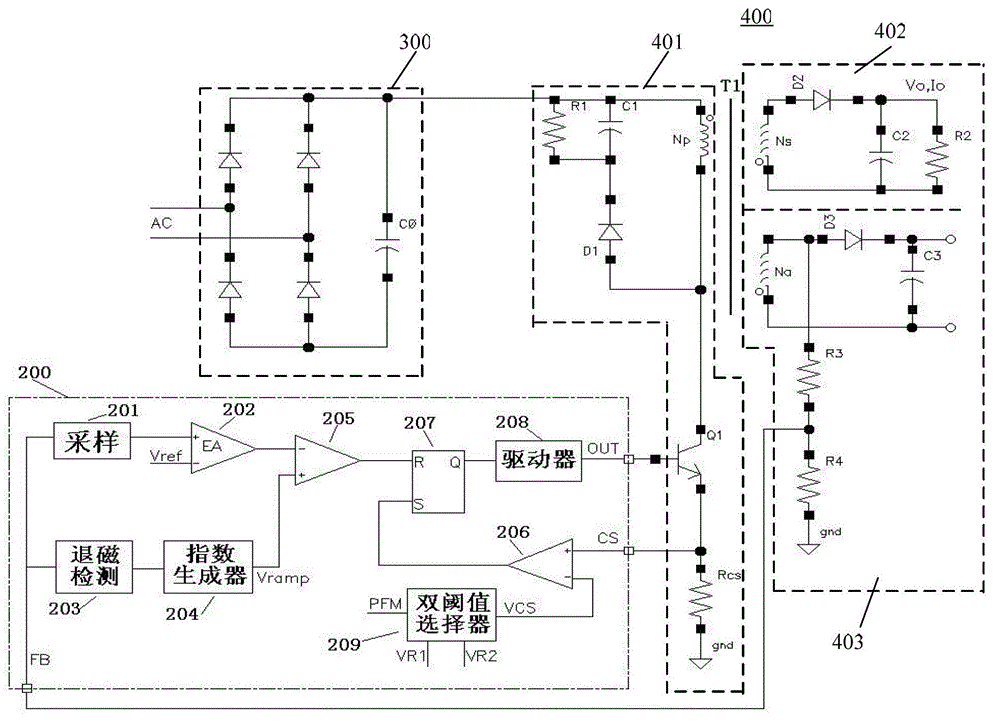
[0025] Such as figure 2 As shown, this embodiment provides a dual-threshold control system for a switching power supply, including a rectifier circuit 300, a conversion circuit 400 connected to the rectification circuit, and a control circuit connected to the conversion circuit 400 for controlling the output voltage Vo of the conversion circuit 400 200.

[0026] Wherein, the conversion circuit 400 includes: a transformer T1, a primary circuit 401 of the transformer T1, a secondary output circuit 402, and an auxiliary stage feedback circuit 403. The output of the auxiliary stage feedback circuit 403 includes the current flowing through the diode D2 in the secondary output circuit 402 of the transformer T1. The feedback signal of the zero-crossing time information is sent to the control circuit 200, and the current flowing through the diode D2 is the current flowing t...


PUM


Abstract

The invention provides a dual-threshold control system and a dual-threshold control method for a switch power supply. The system comprises a rectifying circuit, a converting circuit and a control circuit, wherein the converting circuit is connected with the rectifying circuit, the control circuit is connected with the converting circuit and is used for controlling the output voltage of the converting circuit, and a dual-threshold selector is arranged in the control circuit. According to the dual-threshold control system and the dual-threshold control method for the switch power supply, through the additional arrangement of the dual-threshold selector, the selector can select different output thresholds according to the output load weight of the system. When the system is changed from the light load into the heavy load, the dual-threshold selector can timely regulate the output threshold, further, the switching-on time of a switch tube Q1 is timely regulated, the dynamic response speed of the system is accelerated, the output voltage ripple of the system is reduced, and the transformer noise caused by sudden load changes cannot be heard by people.

Description

technical field [0001] The invention relates to the technical field of switching power supplies, in particular to a dual-threshold control system and method for switching power supplies. Background technique [0002] The electricity generated by the electric field cannot be used directly in many cases, and it must be converted into electrical energy before it can be used. For example, the use of transformers and frequency converters can convert one form of electrical energy into another form of electrical energy. The circuit that realizes this electrical energy conversion is a switching converter circuit. Among them, the switching converter circuit with closed-loop control and protection links is switch power supply. [0003] figure 1 Shown is a traditional pulse frequency modulation (Pulse frequency modulation, PFM) flyback AC-DC switching power converter circuit, including: a rectifier circuit 300, a converter circuit 400 connected to the rectifier circuit 300 and a conv...

Claims


Application Information

Patent Timeline
Patent Type & Authority Applications(China)
IPC IPC(8): H02M7/217H02M3/335H02M1/14
Inventor 张君志
Owner SHENZHEN FM ELECTRONICS GRP CO LTD
Learn More