Video image color compensation method and device based on numerical control optical fiber

An optical filter and color compensation technology, which is applied in projection devices, image reproducers using projection devices, instruments, etc., can solve the problems of reducing the color reproduction degree of projection devices, color distortion of projection devices, and impossible uniform distribution of colors, etc. Achieve the effects of enhancing color reproduction, compensating for filter distortion, and perfect reproduction ability

Inactive Publication Date: 2013-06-12
EAST CHINA NORMAL UNIVERSITY
View PDF3 Cites 5 Cited by
  • Summary
  • Abstract
  • Description
  • Claims
  • Application Information

AI Technical Summary

Problems solved by technology

[0004] Because in the single-chip DMD projection system, only one light filtering process is performed at the same time, and only one color of light passes through each time, so it will bring some loss of brightness
At the same time, due to the differences in the inherent characteristics of the spectral wavelength of different colors of light, there are differences in color reproduction.
In the actual color filter, due to process problems, each color cannot be evenly distributed and perfectly transitioned to the next color, which makes the color reproduction distorted. This phenomenon is most obvious when the filter turns to the edge of each color
Due to the color distortion of the optical filter itself, the color of the entire projection device is distorted, which greatly reduces the color reproduction of the projection device

Method used


Image

  • Video image color compensation method and device based on numerical control optical fiber
  • Video image color compensation method and device based on numerical control optical fiber
  • Video image color compensation method and device based on numerical control optical fiber

Examples


Embodiment Construction

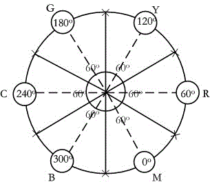
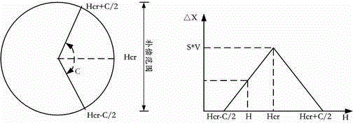
[0025] refer to figure 1 , is the structure of digitally controlled optical filter. The numerical control optical filter is composed of 6 different color filters of red (R), green (G), blue (B), yellow (Y), magenta (M) and cyan (C), which are evenly distributed to form a circle (360°), that is, from an angle, each color filter occupies 60°. The central angle Hcr of each color filter is defined as red 60°, green 180°, blue 300°, yellow 120°, magenta 0° or 360°, cyan 240°; Digital control of the filter, time-division multiplexing of 6 kinds of color filters, can effectively expand the range of color expression.

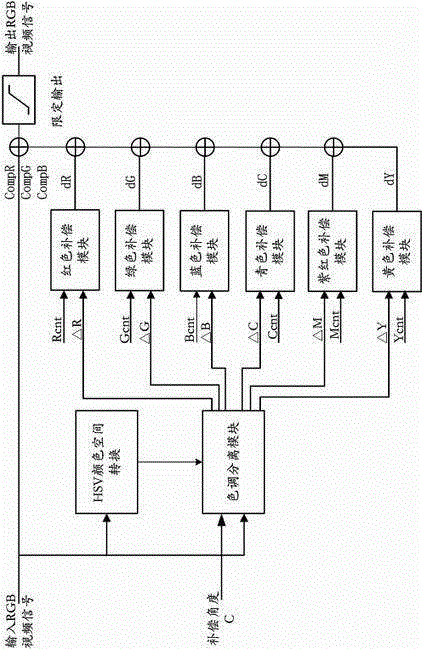
[0026] refer to image 3 ,is directed at figure 1 The specific tone compensation circuit designed for the digitally controlled optical filter structure. It mainly includes the following modules: HSV color space conversion module, hue separation module, color compensation module (RGBYCM) and limited output module.

[0027] a. The HSV color space conversion module r...


PUM


Abstract

The invention discloses a video image color compensation method and device based on a numerical control optical fiber. The device comprises a digital mirror driving plate, a digital mirror device (DMD), a numerical control optical filer and a light source UHP (ultra high pressure) lamp, wherein the digital mirror driving plate comprises an FPGA (field programmable gate array) and a microcontroller ARM (advanced RISC machines), wherein the FPGA is a nuclear processor of a system which is used for realizing color compensation and finally driving the DMD; while the microcontroller ARM is used for driving the numerical control optical filer so as to ensure high speed rotation of the numerical control optical filer; the light source UHP lamp is the light source of the DMD; the numerical control optical filer is used as a color filter of the light source, and only single-colored light of the white light emitted by the light source at every moment can illuminate the DMD by the numerical control optical filter. Aiming at the filter distortion of the numerical control optical filer, the method and device provided by the invention can be used for enhancing the color reproduction displayed by the video images.

Description

technical field [0001] The invention relates to the technical field of optical filter processing, in particular to a video image color compensation method and device based on a numerically controlled optical filter. Background technique [0002] An optical filter is an instrument used for wavelength selection, which can select the desired wavelength from many wavelengths and reject light other than this wavelength. Any technology that can select light can be used to manufacture optical filters in principle, so there are many forms of optical filters. In digital light processing (DLP) display technology, it is necessary to use optical filters to complete the separation and processing of colors, so as to realize color projection display. Here, a color filter is used to realize the optical filter, which can accurately select the small-range band of light waves to pass, and reflect other bands that do not want to pass through. Usually, the color filter is installed in front of...

Claims


Application Information

Patent Timeline
IPC IPC(8): H04N9/31G03B21/00G03B21/14
Inventor 刘一清顾晓丽
Owner EAST CHINA NORMAL UNIVERSITY
Why Eureka
Try Eureka