LED lamps

A technology of light-emitting diodes and lamps, which is applied in the direction of light sources, electric light sources, and electric lamp circuit layout, etc., can solve the problems of inability to meet requirements, difficult control of afterglow circuits, and difficult design.

Active Publication Date: 2016-04-20
HOTALUX LTD
View PDF5 Cites 0 Cited by
  • Summary
  • Abstract
  • Description
  • Claims
  • Application Information

AI Technical Summary

Problems solved by technology

[0004] 1. Because when the LED lamp adopts a high working voltage, the working current is small and the driver efficiency is high, so the working voltage of the light source 95 is generally higher than DC15V, and the built-in power storage unit 93 generally adopts energy storage elements such as supercapacitors or batteries, The voltage of its single unit is only a few volts. If the light source 95 is used as the residual light source, it is necessary to use multiple supercapacitors or batteries in series, otherwise a booster circuit is required, which will not only increase the cost, but also occupy the circuit board configuration. space, creating difficulties in designing
[0005] 2. Sometimes you want the color of the residual light source to be different from that of the main light source. When there is only one set of light sources 95, you can only use the same set of colors. Once the main light source and the residual light source have different color requirements, it will not be able to meet the requirements demand, thus losing the competitiveness of the product
[0006] 3. Due to the brightness requirements of the light source 95, high-power light-emitting diodes must be used to meet the required brightness
In the case of using a high-power light-emitting diode as the afterglow light source, its rated current value is about several hundred times the afterglow working current, which will make the afterglow circuit difficult to control; using an independent low-power LED as the afterglow LED, its rated current The value is about dozens of times of the afterglow working current, and because the current feedback resistor can be set independently, the design of the afterglow circuit is simple
[0007] 4. When the power supply is cut off, since the afterglow light source is forced to emit light, it cannot meet the demand that does not require the afterglow light source to emit light
[0008] 5. When the power supply is cut off through the switch on the wall, the switching control unit switches to the afterglow light source, but in the case of using the remote control or using power line communication to control the light off, since the commercial power supply is not cut off, the afterglow The light source does not emit light, so the brightness cannot be guaranteed to be visible to the side

Method used


Image

  • LED lamps
  • LED lamps
  • LED lamps

Examples


Embodiment Construction

[0041] The present invention discloses a light emitting diode lamp, wherein the principle of the light emitting diode used has been understood by those skilled in the art, so the following description will not be fully described. At the same time, it is stated in advance that the drawings compared below are schematic structural representations related to the features of the present invention, and are not and need not be completely drawn according to actual dimensions.

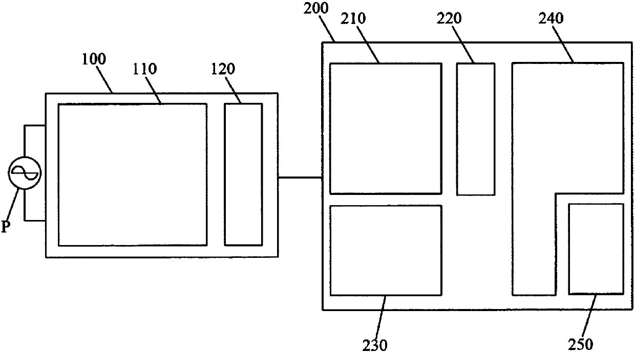
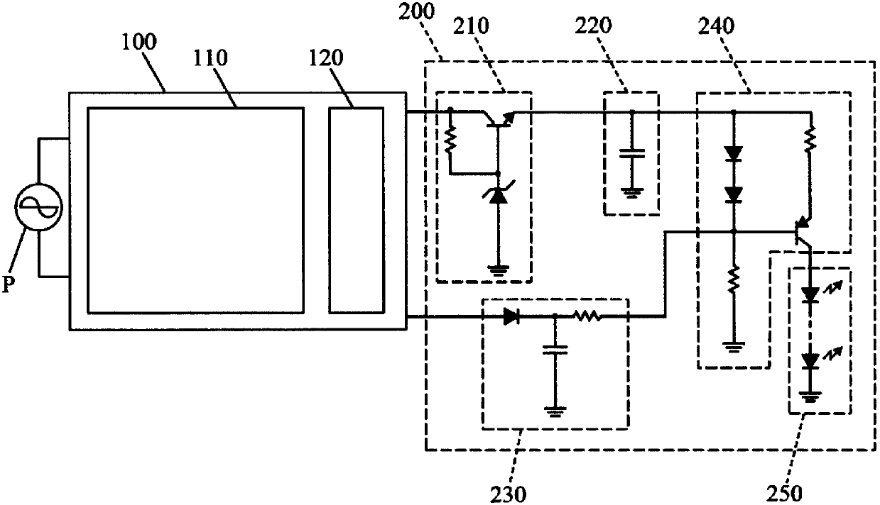
[0042] Please refer to figure 2 It is a structural block diagram of the light-emitting diode lamp proposed by the present invention. The LED lamp of the present invention comprises a main lighting circuit module 100 and an afterglow circuit module 200 electrically connected to the main lighting circuit module 100 .

[0043] The components constituting the aforementioned main lighting circuit module 100 include a main lighting driving device 110 and a main lighting load 120 . The main lighting load 120 is electr...


PUM


Abstract

PROBLEM TO BE SOLVED: To provide a novel light-emitting diode lamp including a main lighting circuit module and an afterglow circuit module electrically connected to each other.SOLUTION: In a light-emitting diode lamp of the present invention, an afterglow circuit module has a DC constant voltage device, and the DC constant voltage device obtains DC voltage from a main lighting circuit module and further supplies stable DC voltage to the afterglow circuit module. When a power source is turned on, the DC constant voltage device supplies charging voltage to an energy storage element in the afterglow circuit module, whereas when the power source is cut off, the energy storage element discharges electricity to the afterglow circuit module. The afterglow circuit module further includes a current control unit which drives an afterglow lighting load.

Description

technical field [0001] The invention relates to a light-emitting diode lamp using light-emitting diode technology, in particular to provide a light-emitting diode lamp with both main lighting load and afterglow lighting load. When the main lighting load is extinguished, the afterglow lighting load is used as an auxiliary afterglow light source. Background technique [0002] Generally, after the lamps used as the main lighting are turned off, the darkness will make the human eyes unable to distinguish the direction immediately. At this time, we can only wait for the eyes to adapt to the environment. In order to solve this problem, please refer to figure 1 , is a known architecture block diagram of a dimming lighting fixture after a power failure. In this known dimming lighting fixture after power failure, a charging control unit 92 , a built-in storage unit 93 , a dimming drive control unit 94 , a switching control unit 96 and a light source 95 are provided in the lamp body ...

Claims


Application Information

Patent Timeline
Patent Type & Authority Patents(China)
IPC IPC(8): H05B37/02
CPCY02B20/40
Inventor 藤川隆浩田中正昭庄斐志
Owner HOTALUX LTD
Why Eureka
Try Eureka