Electrode, electrically heated catalytic converter using same and process for producing electrically heated catalytic converter

一种催化剂装置、制造方法的技术,应用在电极领域,能够解决电极龟裂、剥离等问题,达到电阻值抑制的效果

Inactive Publication Date: 2013-06-12
TOYOTA JIDOSHA KK
View PDF4 Cites 9 Cited by
  • Summary
  • Abstract
  • Description
  • Claims
  • Application Information

AI Technical Summary

Problems solved by technology

Therefore, there is a problem that the difference in linear expansion coefficient between the metal material constituting the electrode and the ceramic material constituting the carrier causes cracking or peeling of the electrode, etc.

Method used


Image

  • Electrode, electrically heated catalytic converter using same and process for producing electrically heated catalytic converter
  • Electrode, electrically heated catalytic converter using same and process for producing electrically heated catalytic converter
  • Electrode, electrically heated catalytic converter using same and process for producing electrically heated catalytic converter

Examples


Embodiment approach 1

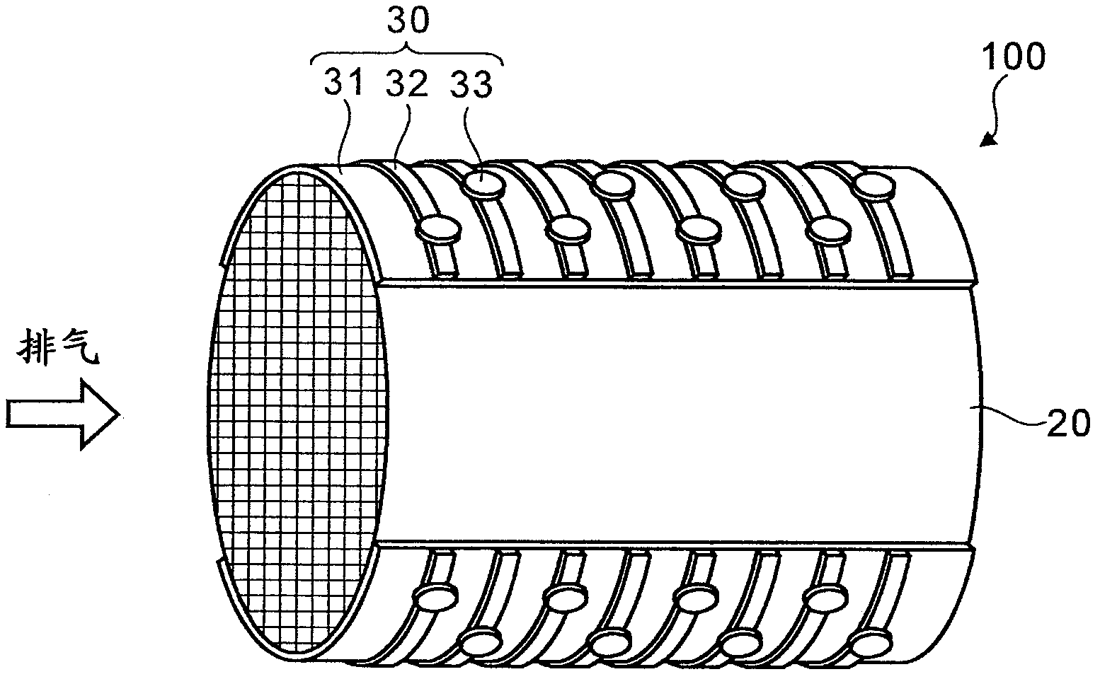
[0070] First refer to figure 1 , figure 2 The electrically heated catalyst device according to this embodiment will be described. figure 1 It is a perspective view of the electrically heated catalyst device 100 according to the first embodiment. The electrically heated catalyst device 100 is installed, for example, in an exhaust port of an automobile, and is used to purify exhaust gas discharged from the engine. like figure 1 As shown, the electrothermal catalyst device 100 includes a carrier 20 and an electrode 30 .

[0071] The carrier 20 is a porous member for supporting a catalyst such as platinum or palladium. In addition, the carrier 20 itself is made of conductive ceramics, specifically SiC (silicon carbide), for example, since it is heated by energization. like figure 1 As shown, the carrier 20 is cylindrical in shape and has a honeycomb structure inside. As indicated by the arrow, the exhaust gas passes through the inside of the carrier 20 along the axial dire...

Embodiment 1)

[0110] By a gas atomization method, substrate particles having a particle diameter of 10 to 50 μm (average particle diameter of 30 μm) formed of a Ni-50% by mass Cr alloy constituting the metal substrate were produced.

[0111] On the other hand, dispersed phase particles comprising bentonite having a particle diameter of 10 to 50 μm (average particle diameter of 30 μm) constituting the dispersed phase were produced by a spray drying method. The particles were sintered at a temperature of 1050° C. in a hydrogen atmosphere.

[0112] Next, the matrix particles and the dispersed phase particles were composited by kneading and granulation using a polymeric binder as a medium, and sintered at a temperature of 1050°C in a hydrogen atmosphere to produce particles for spraying.

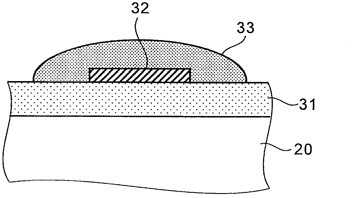
[0113] Next, the aforementioned particles for spraying were plasma sprayed onto the surface of the carrier 20 made of SiC to form a base layer 31 with a thickness of 150 μm.

[0114]Next, a metal foil 32 wit...

Embodiment 2)

[0118] A fusion coating was formed in the same manner as in Example 1 except that the area ratio of the dispersed phase was 60%. As a result, the resistance after thermal cycling was 2.8Ω, which is very good.

[0119] here Figure 16 This is a photograph of the cross-sectional structure of the fusion coating according to Example 2.


PUM

PropertyMeasurementUnit
particle diameteraaaaaaaaaa

Abstract

One embodiment of the present invention pertains to an electrode which is to be formed on a substrate consisting of a ceramic. The electrode is provided with: a matrix which consists of an Ni-Cr alloy (wherein the Cr content is 20 to 60 mass%) or an MCrAlY alloy (wherein M is Fe, Co, and / or Ni); and a dispersed phase which consists of an oxide mineral having a layer structure and which is dispersed in the matrix. In the cross section of the electrode, the area fraction of the dispersed phase is 40 to 80%. By virtue of such a configuration, the increase in the electric resistance of the electrode can be minimized even after the electrode has undergone heat cycles.

Description

technical field [0001] The present invention relates to an electrode, an electrically heated catalyst device using the electrode, and a method for manufacturing the electrically heated catalyst device. Background technique [0002] In recent years, an electrically heated catalyst (EHC: Electrically Heated Catalyst) has attracted attention as an exhaust purification device for purifying exhaust gas discharged from an engine of an automobile or the like. EHC can forcibly activate the catalyst by energizing and heating even under conditions such as immediately after the engine is started where the exhaust gas temperature is low and the catalyst is difficult to activate, thereby improving the purification efficiency of the exhaust gas. [0003] The EHC disclosed in Patent Document 1 has a cylindrical carrier having a honeycomb structure on which a catalyst such as platinum or palladium is supported, and a pair of electrodes electrically connected to the carrier and arranged to f...

Claims


Application Information

Patent Timeline
Patent Type & Authority Applications(China)
IPC IPC(8): H05B3/03
CPCH05B2203/024H05B3/08H05B3/42H05B2203/022F01N3/20H05B3/03
Inventor 下田健二西尾和晃木下靖朗高垣忠史
Owner TOYOTA JIDOSHA KK
Why Eureka
Try Eureka