Tubing chipless cutting device

A technology for cutting devices and pipes, which is applied in the direction of pipe shearing devices, shearing devices, and accessories for shearing machines, etc.

Active Publication Date: 2013-06-19
海亦(河南)机械有限公司
View PDF8 Cites 5 Cited by
  • Summary
  • Abstract
  • Description
  • Claims
  • Application Information

AI Technical Summary

Problems solved by technology

[0005] The purpose of the present invention is to overcome the problems existing in the existing pipe cutting methods, and provide a new type of pipe chip

Method used


Image

  • Tubing chipless cutting device
  • Tubing chipless cutting device
  • Tubing chipless cutting device

Examples


Embodiment Construction

[0022] In order to further explain the technical means and effects of the present invention to achieve the intended purpose of the invention, the specific implementation, structure, characteristics and details of the chipless cutting device for pipes proposed according to the present invention will be described below in conjunction with the accompanying drawings and preferred embodiments. Efficacy, detailed as follows.

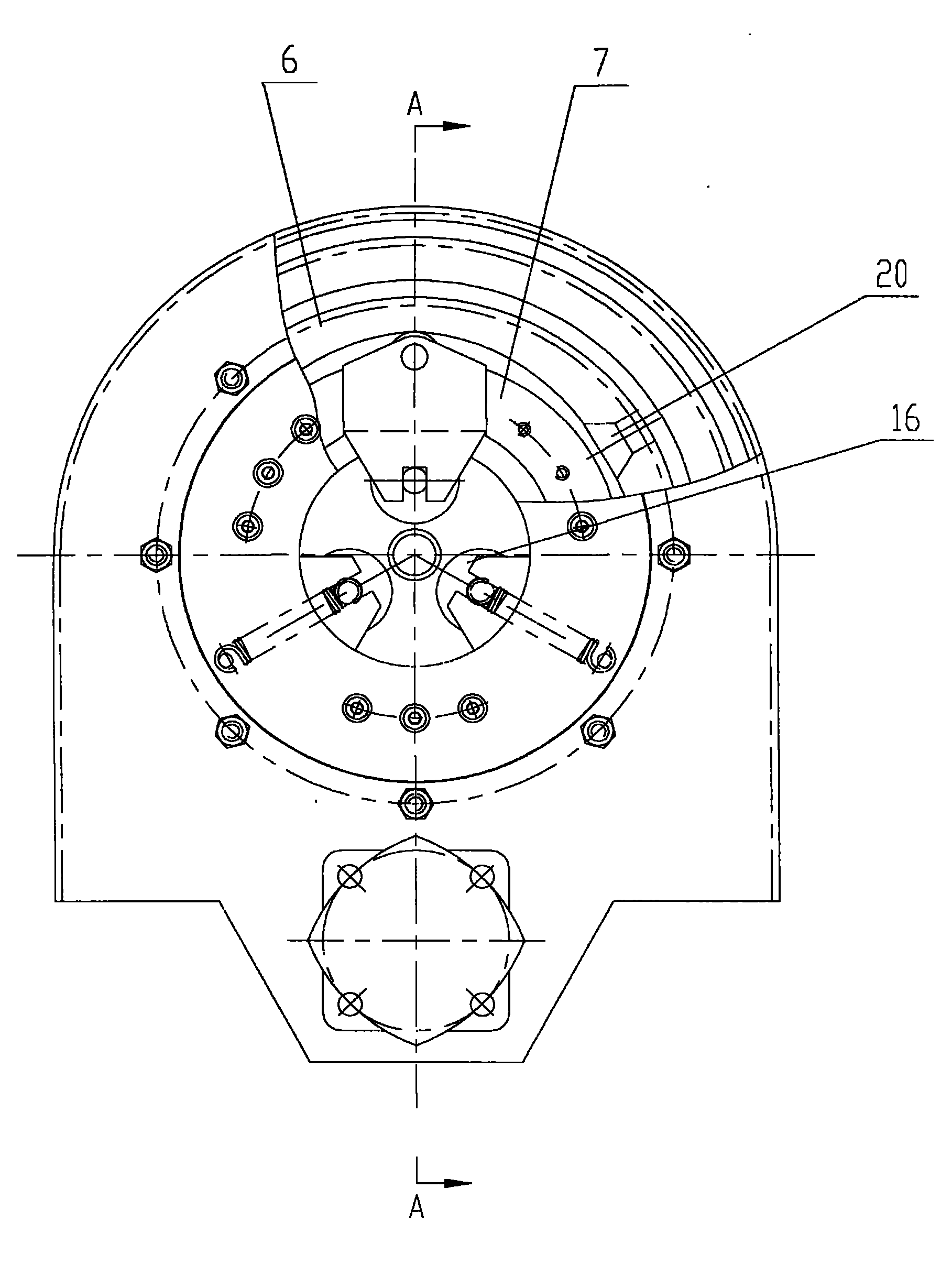
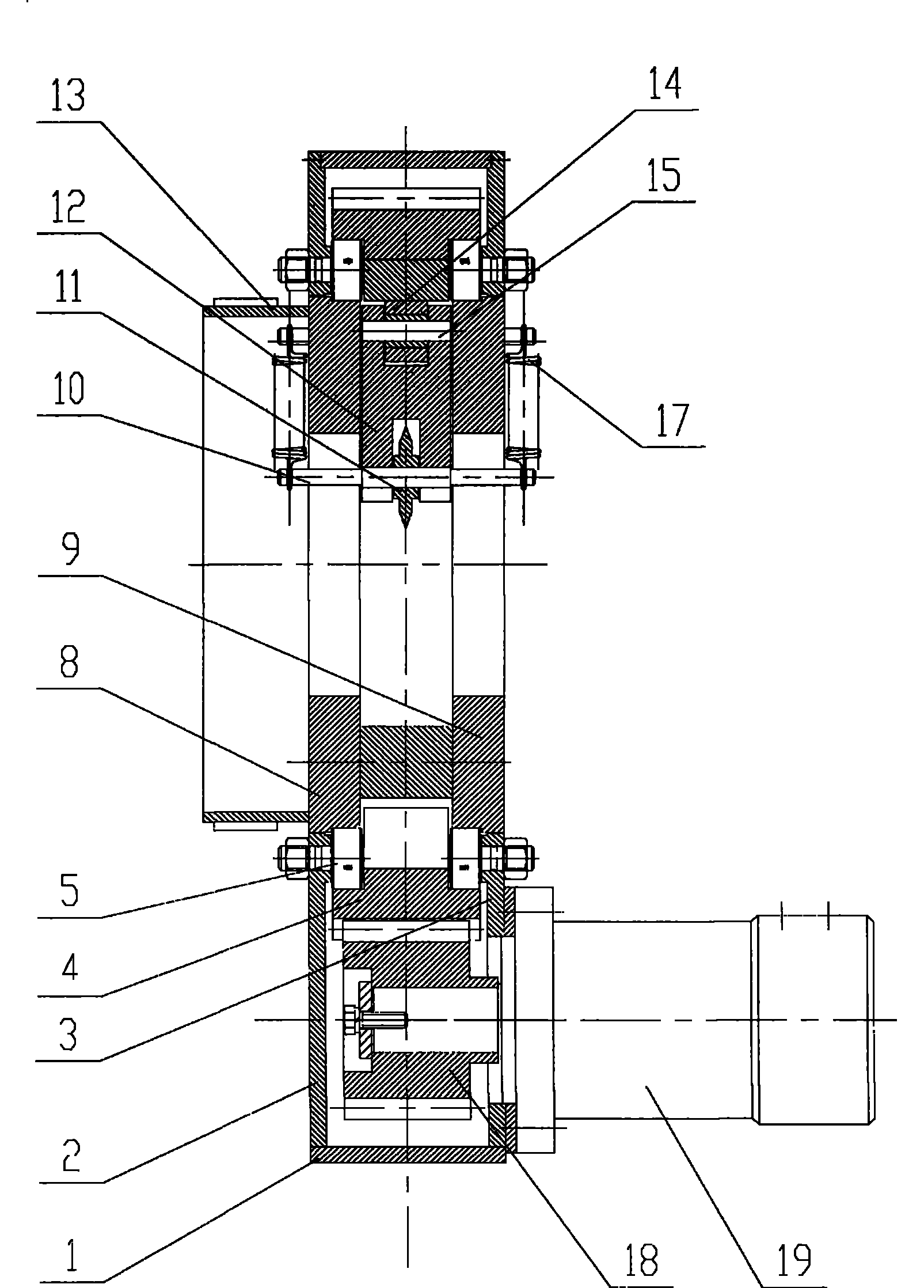
[0023] The structure of the pipe chip-free cutting device of the present invention is as attached figure 1 And attached figure 2 shown.

[0024] figure 1 and figure 2 The chip-free cutting device for pipes includes: body device, transmission system, clamping mechanism and pre-tensioning mechanism, etc.

[0025] The body device includes: a body 1, a left end cover 2, a right end cover 3, and a bolt support roller set 5 installed on the left end cover 2 and the right end cover 3, etc.

[0026] The transmission system includes: a hydraulic motor 19, a smal...


PUM


Abstract

The invention discloses a tubing chipless cutting device. The tubing chipless cutting device comprises a machine body device, a driving system, a clamping mechanism and a pre-tight mechanism. The machine body device comprises a machine body (1), a left end cover (2), a right end cover (3) and a bolt supporting roller group (5), wherein the bolt supporting roller group is installed on the left and the right end covers (2,3). The driving mechanism comprises a hydraulic motor (19), a pinion (18) and a big gear wheel (4). The clamping mechanism comprises three climbing liner plates (6) of an inner circle of the big gear wheel (4), three sector blocks (7), a left lateral plate (8), a right lateral plate (9) and three sliding blocks (12). The pre-tight mechanism comprises a cylindrical brake cylinder (13), a brake band (21), a connecting plate (23), a screw pillar (22) and a nut (24), wherein the cylindrical brake cylinder (13) is connected with the left lateral plate (8), the brake band (21) is installed outside the cylindrical brake cylinder (13), and the connecting plate (23) can connected the brake band (21) on the left end cover (2). The tubing chipless cutting device can improve cutting efficiency and avoid environmental pollution.

Description

technical field [0001] The invention relates to a non-ferrous metal pipe processing technology, in particular to a non-ferrous metal pipe chip-free cutting device. Background technique [0002] Existing production lines for processing non-ferrous alloy pipes such as copper and aluminum usually use manual cutting to cut the pipes. For example, workers use electric saws to cut the pipes taken off the production line to cut the pipes. [0003] The inventor found in the process of realizing the present invention that: the existing way of cutting pipes is off-line (that is, no production line can be formed), not only the cutting efficiency is low, but also the use of electric saws to cut pipes will cause environmental pollution. [0004] In view of the problems existing in the above-mentioned existing pipe cutting methods, the inventor actively researches and innovates based on years of rich practical experience and professional knowledge engaged in the design and manufacture of ...

Claims


Application Information

Patent Timeline
IPC IPC(8): B23D21/04B23D33/02
Inventor 田怀欣胡永志毛青
Owner 海亦(河南)机械有限公司
Why Eureka
Try Eureka