Hydraulic lifter

A hydraulic and lift technology, applied in the direction of lifting devices, etc., can solve the problems of increased motor output, power consumption, and impaired safety

Inactive Publication Date: 2013-06-19
SHIMADZU CORP
View PDF5 Cites 3 Cited by
  • Summary
  • Abstract
  • Description
  • Claims
  • Application Information

AI Technical Summary

Problems solved by technology

However, if the orifice diameter is increased, in Patent Document 1, since the common throttle valve is also used in the descending flow path, the descending speed will be accelerated to the descending speed when a person is riding on the vehicle, resulting in a safety hazard. damage
In addition, if the rotation speed is increased, the output of the electric motor (electric motor) will increase, resulting in excessive power consumption

Method used


Image

  • Hydraulic lifter
  • Hydraulic lifter
  • Hydraulic lifter

Examples


Embodiment Construction

[0042] One embodiment of the present invention will be described below.

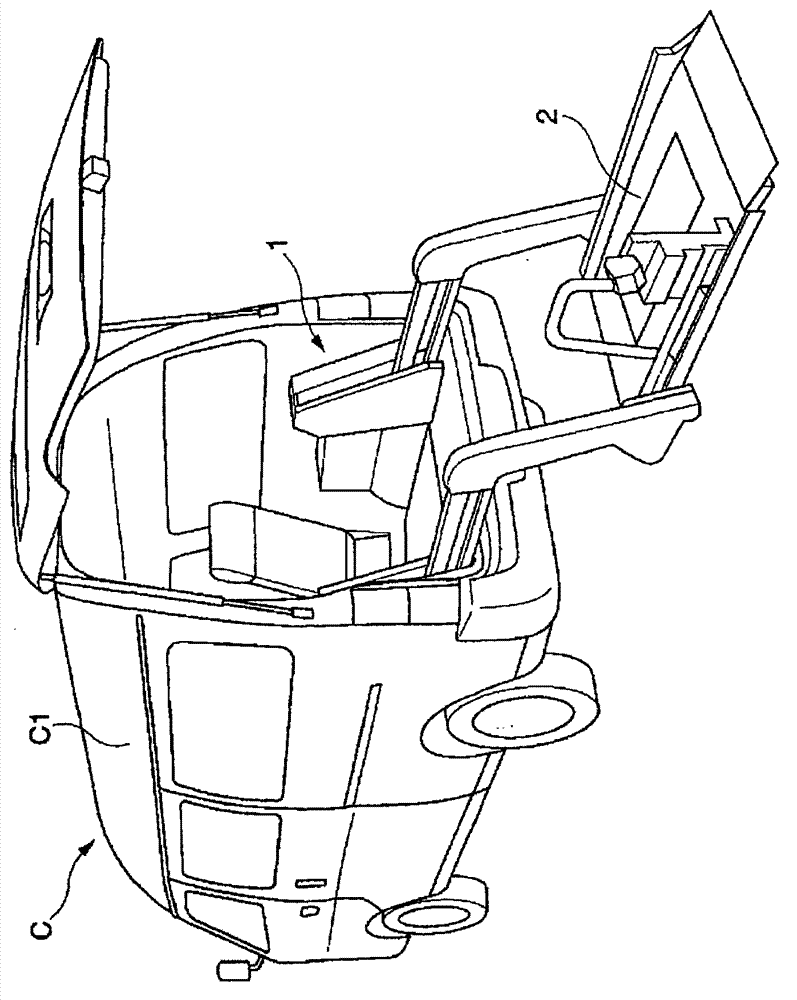
[0043] Such as figure 1 As shown, the vehicle C of this embodiment includes: a vehicle body C1, and a hydraulic lift 1 provided at the rear of the vehicle body C1.

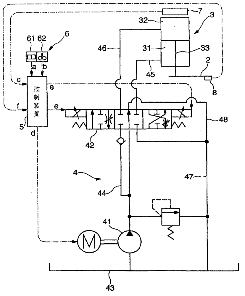
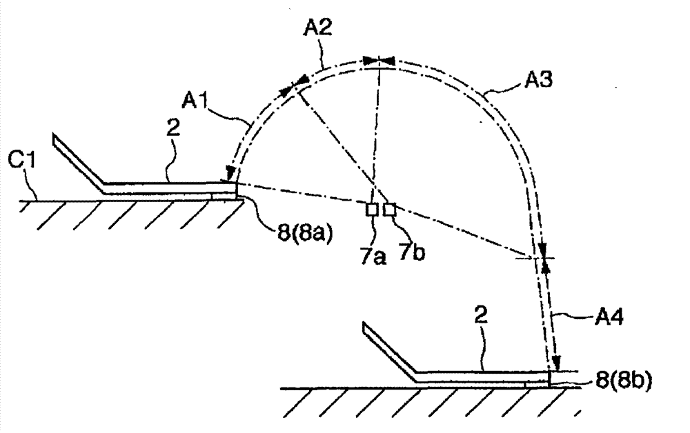
[0044] Such as figure 2 As shown, the hydraulic lift 1 includes: a lifting plate 2 for taking a person in need of care; an actuator 3 to drive the lifting plate 2; a hydraulic unit 4 including a hydraulic pump 41 and a proportional valve 42, The hydraulic pump 41 is connected to the motor M as a driving source, and hydraulic pressure is supplied to the actuator 3. The proportional valve 42 is a valve whose opening degree can be changed. The amount of hydraulic fluid supplied to the actuator 3 is changed; the control device 5 receives the position of the elevator from the position sensor 7 using a proximity sensor or the like in order to control the amount of hydraulic fluid supplied to the actuator 3 etc. to control the rotation speed of...


PUM


Abstract

The invention provides a hydraulic lifter, of which the hydraulic unit comprises a hydraulic pump connected to a motor serving as a driving source and supplies working pressure to a lifting plate to drive an actuator, and a proportional valve which receives the signals form a controller to change opening degree and change the quantity of the work liquid supplied to the actuator via the hydraulic pump. The controller controls the rotation speed of the hydraulic pump and the quantity of the work liquid supplied to the actuator is controlled by the opening degree of the proportional valve. The controller at least carrying following control processes: receiving input of lifting speed of the lifting plate, allowing the motor to rotate at the lowest speed enabling generating torque after a switch starts lifting operation, changing the proportional valve from a fully-closed state to a fully-opened state after the motor rotates in the lowest speed, and gradually increasing the rotating speed of the motor to an object speed corresponding to the elevating speed of the lifting plate received from the switch at the completion of the control of the proportional valve.

Description

technical field [0001] The present invention relates to a hydraulic lift capable of supplying an operating fluid to an actuator through a hydraulic circuit, whereby a lifting plate connected to the actuator is Drive, and the working speed of the lifting plate can be changed by changing the amount of working fluid supplied to the actuator. Background technique [0002] Conventionally, various elevators have been known, and these elevators include: a lifting plate capable of loading a load object; an actuator for driving the lifting plate; a hydraulic circuit for supplying working fluid to the actuator; and a control device for controlling The amount of working fluid supplied to the actuator is controlled. As an example of such an elevator, an elevator can be considered in which the hydraulic circuit includes a hydraulic pump for supplying operating hydraulic pressure to the actuator, and the hydraulic pump is connected to a motor (motor) as a driving source. , the control d...

Claims


Application Information

Patent Timeline
IPC IPC(8): B66F11/04B66F13/00
Inventor 东秀树河内宏充山村真哉
Owner SHIMADZU CORP
Why Eureka
Try Eureka