Ring Roasters for Carbon Production

A ring roasting furnace and carbon technology, which is applied in the preparation/purification of carbon, etc., can solve the problems of depositing tar, the treatment effect of benzopyrene is small, and the consumption of large fuel, etc., to achieve the effect of avoiding cracks.

Active Publication Date: 2016-02-10
GUIYANG AL-MG DESIGN & RES INST
View PDF2 Cites 0 Cited by
  • Summary
  • Abstract
  • Description
  • Claims
  • Application Information

AI Technical Summary

Problems solved by technology

At present, the method of cooling tower + electric tar catcher is mainly used in China to treat flue gas. The equipment is huge and the investment is high. Although the tar and dust in the flue gas can be discharged up to the standard, it has little effect on the treatment of benzopyrene and cannot meet the national emission requirements. Standard requirements, and the collected tar contains a lot of water and dust, which is not easy to recycle and is discarded by many enterprises, causing secondary pollution
Benzopyrene is a carcinogen. Studies have shown that it can only be treated by incineration. The incineration temperature must be above 800°C. Due to the large flow rate and low temperature of the roasting flue gas, a large amount of fuel must be consumed to incinerate the flue gas. No carbon company has taken measures to control the benzopyrene in the flue gas of the annular furnace. Therefore, the excessive emission of benzopyrene in the flue gas of the annular roaster is very common
In addition, the method of cooling tower + electric tar collector cannot completely capture tar. As time goes by, tar will inevitably be deposited on the flue gas pipe, induced draft fan and the bottom of the chimney, resulting in pipe blockage and induced draft fan loss of balance. Even accidents of spontaneous combustion of tar also occur from time to time, and there are certain potential safety hazards

Method used


Image

  • Ring Roasters for Carbon Production
  • Ring Roasters for Carbon Production

Examples


Embodiment Construction

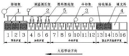
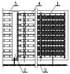
[0026] Embodiment of the present invention: several furnace chambers are connected end to end to form a ring, each ring-type roasting furnace contains 1 to 3 flame systems, and each flame system contains 16 to 18 furnace chambers, of which 3 furnace chambers are preheated ~6, 2~3 heating furnace chambers, 6 cooling furnace chambers, 3~4 furnace chambers for loading and repairing; each furnace chamber includes 4~8 material boxes 4, 5~9 fire channels 5; The material box 4 and the fire channel 5 are separated, and there is no gap between the walls; the furnace cover 1 and the volatile matter pipeline 3 are arranged on the upper part of the material box in the preheating furnace chamber, and the volatile matter combustion frame 2 is arranged on the upper part of the heating furnace chamber. 1. The volatile matter combustion rack 2 is connected with the volatile matter pipeline 3, and the volatile matter combustion rack 2 is connected with the fire path 5 of the heating furnace cham...


PUM


Abstract

The invention discloses a ring-type roasting furnace for carbon production, which is composed of several furnace chambers connected end to end to form a ring shape, and the material box (4) is isolated from the fire path (5); the material box (4) of the preheating furnace chamber Furnace cover (1) is set on the upper part, volatile matter pipeline (3) is set in the middle of the two rows of furnace chambers, volatile matter burning rack (2) is set on the upper part of the heating furnace chamber, furnace cover (1), volatile matter burning rack (2) and volatile matter The pipeline (3) is connected, and the volatile matter combustion rack (2) is connected with the fire path (5) of the heating furnace chamber; the furnace cover (1) is provided with an outlet for asphalt volatile matter, and the volatile matter pipe (3) discharges the volatile matter of the furnace cover The discharge port is connected with the inlet of the volatile matter burner (2). The invention avoids the pollution caused by the volatile components of asphalt entering the roasting flue gas and can reduce the roasting energy consumption. At the same time, benzopyrene can also be effectively treated to achieve the purpose of clean production, and it can also avoid the roasting products caused by the high temperature in the preheating stage. Cracks occur.

Description

technical field [0001] The invention relates to a ring type roasting furnace for carbon production. Background technique [0002] In the carbon industry at home and abroad, carbon products are generally roasted in an open ring roaster and a covered ring roaster. The volatile components of pitch in both furnace types enter the roasting flue gas during the preheating stage. On the one hand, the flue temperature in the preheating furnace chamber is low, and the volatile components cannot be fully burned. On the other hand, the roasting of some products (such as cathodes and electrodes) requires strict control of the temperature in the preheating furnace chamber, and a large amount of volatile components are not allowed to burn, resulting in a large amount The volatile matter is discharged out of the roaster along with the flue gas. [0003] The main harmful components of asphalt volatiles are tar, benzopyrene, and carbon dust. At present, the method of cooling tower + electri...

Claims


Application Information

Patent Timeline
Patent Type & Authority Patents(China)
IPC IPC(8): C01B31/02C01B32/05
Inventor 谢志群谢斌兰陈宁
Owner GUIYANG AL-MG DESIGN & RES INST
Why Eureka
Try Eureka