
Biofilter

A biofilter and biofilter technology, applied in the direction of biological treatment devices, sustainable biological treatment, biological water/sewage treatment, etc., can solve the problems of separately setting blowers and air distributors, and achieve construction costs and operation and maintenance costs The effect of reducing and increasing the removal rate

Inactive Publication Date: 2013-06-19
BOE TECH GRP CO LTD +1
View PDF8 Cites 2 Cited by
  • Summary
  • Abstract
  • Description
  • Claims
  • Application Information

AI Technical Summary

Problems solved by technology

[0006] In order to solve the technical problem that the existing biological aerated filter requires a separate blower and air distributor, the present invention provides a biological filter, which greatly reduces the construction cost and operation and maintenance cost, and ensures the uniform oxygenation of all parts in the filter

Method used


Image

  • Biofilter
  • Biofilter
  • Biofilter

Examples


Embodiment Construction

[0030] The structure and principle of the present invention will be described in detail below in conjunction with the accompanying drawings, and the examples given are only used to explain the present invention, not to limit the protection scope of the present invention.

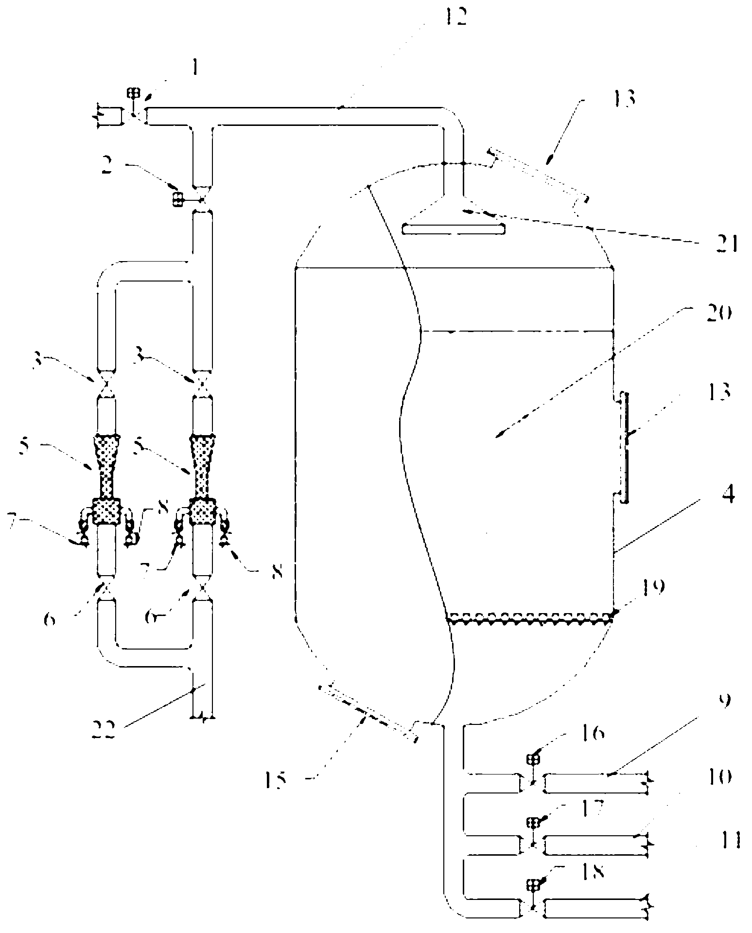
[0031] Such as figure 2 As shown, the present embodiment provides a biological filter, comprising:

[0032] Biofilter 4 for containing biological filler;

[0033] The water inlet pipeline 22 that is provided with ejector 5, the two ends of described water inlet pipeline 22 are respectively provided with the water inlet that is connected with lifting pump, and extend from the top of described biofilter 4 to the inside of described biofilter 4 the water outlet;

[0034] A water outlet pipe 9 communicating with the water outlet at the bottom of the biofilter 4 .

[0035] The jet device 5 is used to fully oxygenate the waste water entering the biofilter 4, to ensure the uniform oxygenation of all parts in th...


PUM


Abstract

The invention relates to a biofilter which comprises a biological filter for containing biological filler, a water inlet pipeline, an ejector, a lifting pump and a water outlet pipeline, wherein a water inlet and a water outlet extending from the top of the biological filter into the biological filter are formed at the two ends of the water inlet pipeline respectively; the ejector is used for oxygenating water entering the water inlet pipeline and is arranged on the water inlet pipeline; the lifting pump is used for increasing pressure of the water entering the water inlet pipeline and is arranged at the water inlet of the water inlet pipeline; and the water outlet pipeline is communicated with the water outlet at the bottom of the biological filter. The biofilter provided by the invention has the beneficial effects that the problem that an independent aeration device is required in the prior art is solved by adopting the ejector, and the construction cost and the maintenance cost are remarkably reduced; and moreover, the incoming water is sufficiently oxygenated, uniform oxygenation at each part in the biological filter is guaranteed, and the pollutant removal rate is obviously improved.

Description

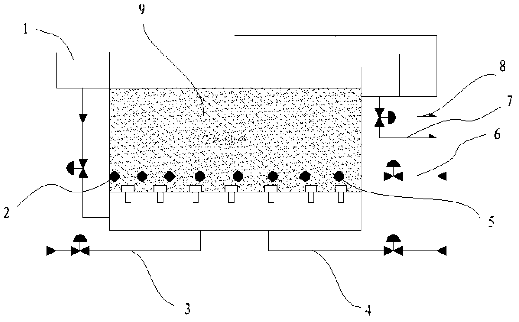
technical field [0001] The invention relates to the technical field of wastewater treatment, in particular to a biological filter. Background technique [0002] Various biological aerated filters exist, such as figure 1 Shown: Biological aeration filter includes: water distribution tank 1, single-hole membrane air diffuser 2, backwash water inlet pipe 3, backwash inlet pipe 4, filter head 5, aeration pipe 6, backwash drain pipe 7, normal Drainage pipe 8, biological filter material 9, the water is pumped to the water distribution tank 1 through the pump, and enters the biological filter tank from the bottom through the water distribution pipe, and the water flows from bottom to top. The water is discharged from the normal drainage pipe 8. During this process, the blower needs to be started to provide air to the biofilter through the aeration pipe 6 and the single-hole membrane air diffuser 2. [0003] The existing biological aerated filter has the following deficiencies: ...

Claims


Application Information

Patent Timeline
IPC IPC(8): C02F3/02
CPCC02F3/04C02F3/106C02F3/107C02F2203/006C02F2303/16Y02W10/10
Inventor 冯济武
Owner BOE TECH GRP CO LTD
Learn More