Non-contact circular weaving machine directly driven through electromagnetism

A non-contact circular loom technology, applied to circular looms, looms, textiles, etc., can solve problems such as complex structure, large frictional resistance, and loud noise, and achieve stable and reliable operation, reduce frictional resistance, and reduce energy consumption Effect

Active Publication Date: 2013-06-19
TAIZHOU CITY JIANGYAN DISTRICT XINHUILAI TEXTILE MACHINERY CO LTD
View PDF11 Cites 5 Cited by
  • Summary
  • Abstract
  • Description
  • Claims
  • Application Information

AI Technical Summary

Problems solved by technology

At present, the driving and transmission devices of the above-mentioned circular loom usually have many components and complex...

Method used


Image

  • Non-contact circular weaving machine directly driven through electromagnetism
  • Non-contact circular weaving machine directly driven through electromagnetism

Examples


Embodiment Construction

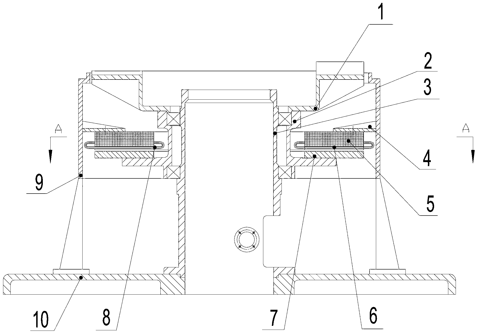
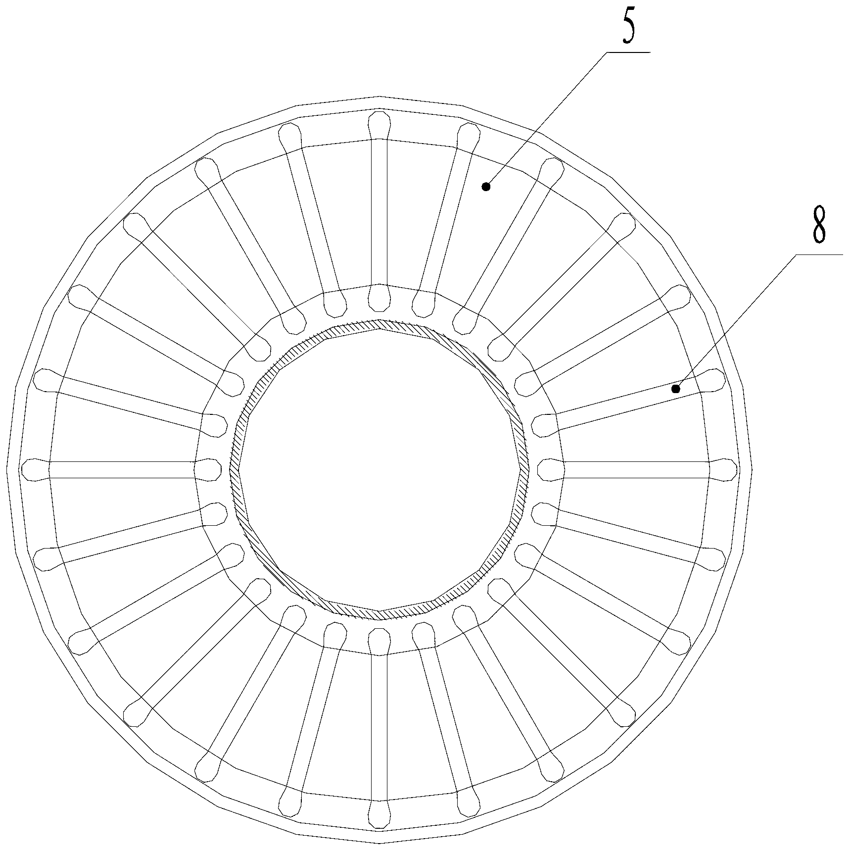
[0017] Such as figure 1 and figure 2 As shown, the circular loom directly driven by the non-contact electromagnetic includes a chassis 10, a central column 3 and a ring sleeve 9, and the central column 3 and the ring sleeve 9 are respectively connected and fixed to the chassis 10, and the center column 3 and the ring sleeve 9 are connected and fixed. There is a shuttle bed 1 between them, the shuttle bed 1 is connected with the center column 3 through the bearing seat 2 and can rotate around the center column 3, and a direct drive planar motor for driving the shuttle bed 1 to rotate around the center column 3 is provided under the shuttle bed 1 , the planar motor is composed of a stator 5 and a rotor 7, the stator 5 is connected and fixed with the ring sleeve 9 through the mounting bracket 4, and the rotor 7 is connected and fixed with the shuttle bed 1 through the bearing seat 2. The stator 5 is provided with a plurality of wire slots 8, the wire slots 8 are embedded with c...


PUM


Abstract

The invention relates to a non-contact circular weaving machine directly driven through electromagnetism. The non-contact circular weaving machine comprises a chassis, a central column, a loop sleeve and a shuttle carrier. The shuttle carrier is connected with the central column through a bearing seat. A planar motor is arranged below the shuttle carrier. The planar motor is formed by a stator and a rotor. The stator is fixed with the loop sleeve through a mounting support. The rotor is fixed with the shuttle carrier through the bearing seat. The stator is provided with a plurality of wire slots, and a coil is arranged in the wire slots in an embedded mode. The rotor is made of pure iron or a permanent magnet. When the rotor coil is powered on, the rotor rotates under the action of electromagnetic force and drives the shuttle carrier to rotate around the central column. The stator is arranged above the rotor. The distance between the stator and the rotor is 1-5 millimeters. According to the non-contact circular weaving machine, the planar motor is adopted to directly drive the shuttle carrier to rotate, so moving parts are decreased. When the motor works, the stator arranged above the rotor acts on the shuttle carrier through the electromagnetic force, so that the gravity which the shuttle carrier acts on a bearing is decreased and even is completely balanced out. Consequently, the bearing rotates in a relatively suspending state, friction resistance is small, and energy consumption is reduced.

Description

technical field [0001] The invention relates to a circular loom, in particular to a circular loom which uses a non-contact plane motor to directly drive a shuttle bed to rotate. Background technique [0002] Existing circular looms generally include main components such as chassis, housing, center column, shuttle bed and driving device, wherein the housing is also called ring sleeve, and the shuttle bed of circular loom is arranged on the center column and ring sleeve, and the shuttle bed is arranged on the center column and ring sleeve. The bed is connected with the central column through the bearing seat and can rotate around the central column driven by the driving device. The driving device of the existing circular loom is generally a motor and a reducer. The motor transmits the torque to the shuttle bed through the reducer and the gear transmission, and the shuttle bed rotates around the central column. At present, the drive and transmission device of the above-mention...

Claims


Application Information

Patent Timeline
IPC IPC(8): D03D37/00D03D51/00
Inventor 朱根山
Owner TAIZHOU CITY JIANGYAN DISTRICT XINHUILAI TEXTILE MACHINERY CO LTD
Why Eureka
Try Eureka