
Swing mechanism and pumping system and concrete device

A pumping system and concrete technology, which is applied in the direction of mechanical equipment, pumps, building structures, etc., can solve the problems of high cost of use, low transmission efficiency, and increased cost of use, and achieve cost-saving, energy-saving, and convenient installation Effect

Active Publication Date: 2013-06-19
SANY AUTOMOBILE MFG CO LTD
View PDF4 Cites 5 Cited by
  • Summary
  • Abstract
  • Description
  • Claims
  • Application Information

AI Technical Summary

Problems solved by technology

[0007] First, in the swinging process of the pendulum valve cylinder in the prior art, the angle between the pendulum valve cylinder and the rocker arm 4' cannot always be kept at 90 degrees, so the thrust of the pendulum valve cylinder cannot be 100% converted into the rocker arm 4' Swing power, serious energy loss, low transmission efficiency, resulting in relatively high cost of construction machinery
[0008] Second, the ball joint ends of the swing valve cylinder, the swing valve seat 1' and the rocker arm 4' are difficult to process, easy to wear and require frequent lubrication, and the materials used for the spherical bearing 3' are relatively expensive, and the cost of use is relatively high
[0009] Third, the piston rod of the pendulum valve cylinder is exposed to the outside, which requires additional components such as a protective cover, which increases the cost of use
[0010] Fourth, there are many components that make up the swing mechanism, the structure is complicated, and the cost is relatively high

Method used


Image

  • Swing mechanism and pumping system and concrete device
  • Swing mechanism and pumping system and concrete device
  • Swing mechanism and pumping system and concrete device

Examples


Embodiment Construction

[0039] The core of the present invention is to provide a swing mechanism, which has relatively small energy loss, relatively high transmission efficiency and relatively simple structure. In addition, another core of the present invention is to provide a pumping system including the aforementioned rocking mechanism.

[0040] In order to enable those skilled in the art to better understand the technical solutions of the present invention, the present invention will be further described in detail below in conjunction with the accompanying drawings and specific embodiments.

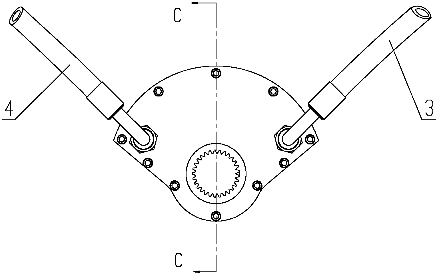
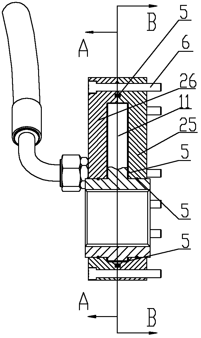
[0041] Please refer to Figure 2 to Figure 6 , figure 2 A structural schematic diagram of a specific embodiment of a rocking mechanism provided by the present invention; image 3 for figure 2 C-C direction sectional view of the rocking mechanism shown; Figure 4 for image 3 The schematic diagram of the cross-sectional view of the rocking mechanism in the A-A direction; Figure 5 for image 3 The sch...


PUM


Abstract

The invention discloses a swing mechanism of a pumping system. The swing mechanism of the pumping system comprises a swing arm. The swing arm comprises a swing portion alternatively driven by a left hydraulic oil way and a right hydraulic oil way and a rotary portion fixedly connected with the swing portion and arranged on a hopper and further comprises a box body provided with a cavity. The swing arm is arranged in the cavity and divides the cavity into a left cavity chamber and a right cavity chamber which are independent. The left side and the right side of the swing portion are respectively communicated with the left hydraulic oil way and the right hydraulic oil way through the left cavity chamber and the right cavity chamber. The rotary portion is in rotary connection with the box body in the circumferential direction. The swing portion of the swing arm in the swing mechanism is directly driven by hydraulic oil, hydraulic pressure energy can be completely converted to motion mechanical energy of the swing portion, and therefore power of a motive power source for driving the swing arm to move is reduced, energy is saved, a structure is simple and occupied space is small. In addition, the invention further discloses the pumping system containing the swing mechanism and a concrete device.

Description

technical field [0001] The invention relates to the technical field of pumping, in particular to a rocking mechanism of a pumping system. In addition, the present invention also relates to a pumping system and concrete equipment comprising the rocking mechanism described above. Background technique [0002] Concrete pumping equipment is a machine that uses pressure to continuously transport concrete along pipelines. It is mainly used in house construction, bridge and tunnel construction, etc. It is a commonly used mechanical equipment in construction machinery. Common concrete pumping equipment includes concrete pump trucks. , tow pump, etc. [0003] Concrete pumping equipment usually includes a delivery cylinder, a hopper, a distribution valve and a swing mechanism. The hopper is used to store concrete; the distribution valve can be driven by the swing mechanism to perform a state transition, and the delivery cylinder is connected to the hopper within a predetermined first...

Claims


Application Information

Patent Timeline
IPC IPC(8): E04G21/04
CPCE04G21/04F04B15/02
Inventor 叶玉全尹腾飞李富龙
Owner SANY AUTOMOBILE MFG CO LTD
Learn More