Heat Exchanger Based on Turboexpander

A technology of a turboexpander and a heat exchange device, which is applied to the components of a pumping device for elastic fluids, mechanical equipment, machines/engines, etc. Disassembly and maintenance, compact structure, reducing the effect of axial heat conduction

Active Publication Date: 2015-10-28
BEIJING ZHONGKE RUIAO ENERGY TECH CO LTD
View PDF5 Cites 0 Cited by
  • Summary
  • Abstract
  • Description
  • Claims
  • Application Information

AI Technical Summary

Problems solved by technology

[0004] In order to solve the problem of complex structure and low efficiency of the existing turbo expander heat exchange device, the present invention provides a heat exchange device based on a turbo expander, including a brake fan, and the brake fan includes an internal fan volute And the outer fan wheel cover arranged around the fan volute, which also includes an integrated heat exchanger sleeved on the periphery of the fan wheel cover, and the heat exchanger is flanged to the fan wheel cover and separated, The flange includes a lower connecting flange connected to the heat exchanger and an upper connecting flange connected to the fan wheel cover

Method used


Image

  • Heat Exchanger Based on Turboexpander

Examples


Embodiment Construction

[0009] The present invention will be further described in detail below in conjunction with the accompanying drawings and specific embodiments.

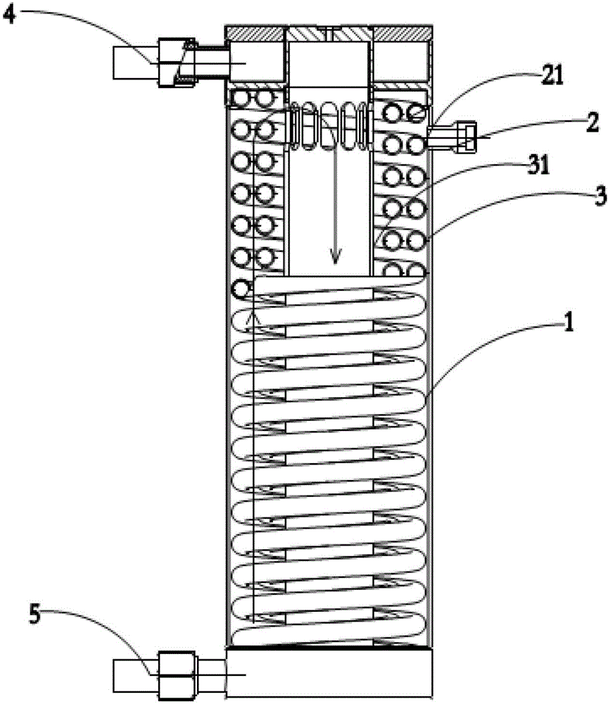
[0010] Such as figure 1 As shown, it is a schematic diagram of the heat exchanger of the heat exchange device based on the turbo expander of the present invention, including a brake fan (not marked), an air intake pipe 2, a cooling water inlet 4 and a cooling water outlet 5, and the brake fan includes The inner fan volute 3 and the outer fan wheel cover (not shown) arranged around the fan volute 3 also include an integrated heat exchanger 1 sleeved on the periphery of the fan wheel cover, and the heat exchanger 1 is connected to the fan wheel cover with a flange (not marked) and separated, and the flange includes a lower connecting flange connected to the heat exchanger 1 and an upper connecting flange connected to the fan wheel cover. The air intake pipe 2 is provided with an outer wall 21 , the fan volute 3 is provided with an inne...


PUM


Abstract

The invention provides a heat exchange device based on a turbo expander. The heat exchange device comprises a braking fan. The braking fan comprises an internal fan volute and an external fan wheel cap which is arranged around the fan volute, and further comprises an integrated type heat exchanger which is sleeved on the periphery of the fan wheel cap. The heat exchanger and the fan wheel cap are connected through a flange and are split. The flange comprises a lower connecting flange and an upper connecting flange, wherein the lower connecting flange is connected with the heat exchanger and the upper connecting flange is connected with the fan wheel cap. The turbo expander is simple and compact in structure.

Description

technical field [0001] The invention relates to a turbo expander, in particular to a heat exchange device based on a turbo expander. Background technique [0002] Most of the existing turboexpander brake fan structures adopt an open cycle, that is, the air is sucked from the atmosphere, and enters the brake fan casing through the silencer filter to brake the turbine rotor system, and the temperature of the gas after braking increases. , into the atmosphere through the exhaust pipe and exhaust muffler. Due to the use of natural cooling, the temperature of the fan casing is often as high as seventy or eighty degrees. In this case, due to the high temperature of the fan casing, it is easy to accelerate the aging of the equipment. At the same time, due to the large temperature difference between the expansion end and the brake end, the axial heat conduction is relatively serious, which will lead to the loss of turbine cooling capacity and reduce the turbine efficiency. Furthe...

Claims


Application Information

Patent Timeline
Patent Type & Authority Patents(China)
IPC IPC(8): F04D29/58
Inventor 孙郁孙立佳赵杰张武
Owner BEIJING ZHONGKE RUIAO ENERGY TECH CO LTD
Why Eureka
Try Eureka