Automatic exhaust valve of heating medium oil system

An automatic exhaust valve, medium oil technology, applied in valve details, valve devices, liquid degassing, etc., can solve the problem that the sealing material rubber of the automatic exhaust valve is not resistant to oil, cannot meet the operation of heat medium oil, and cannot achieve oil-gas separation and other problems, to reduce fire hazards, solve circulation pump evacuation and severe vibration faults, and improve pump efficiency

Active Publication Date: 2013-06-19
PETROCHINA CO LTD
View PDF7 Cites 1 Cited by
  • Summary
  • Abstract
  • Description
  • Claims
  • Application Information

AI Technical Summary

Problems solved by technology

[0004] The vast majority of automatic exhaust valves are used in industrial and civil water supply and drainage processes, and are suitable for normal temperature water vapor occasions. If they are installed in the heat medium oil with hydrocarbons as the main component as the heat transfer medium, there are the following defects: the sealing of the connecting parts The material is rubber, which cannot satisfy the operation of heat medium oil at high temperature (180-220°C); it c

Method used


Image

  • Automatic exhaust valve of heating medium oil system

Examples


Example Embodiment

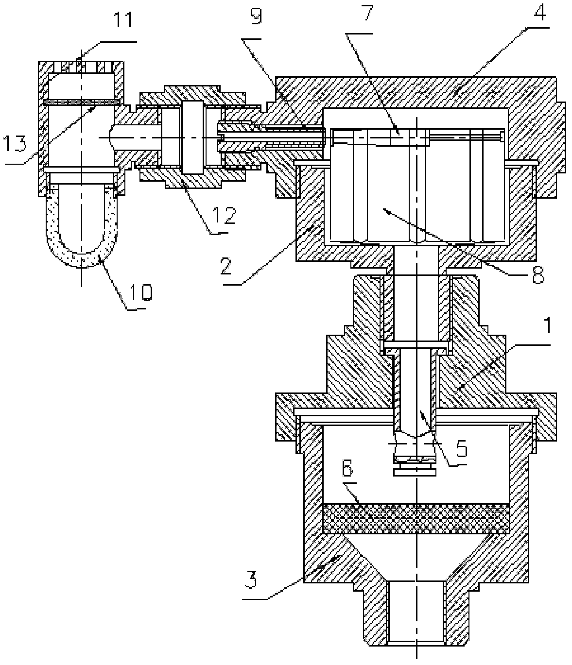
[0016] Such as figure 1 As shown, the gas-liquid separation chamber is set at the bottom of the valve body and consists of a valve seat, a lower valve body, and a filter screen. The internal conical structure and side-opened double-hole drainage and multi-layer filter screen form an ideal collision and gravity In the oil and gas separation chamber, the gas-liquid mixture flows through the mesh filter bed, the gas rises along the fluid channel, and the liquid settles and flows back into the pipe to achieve preliminary oil and gas separation; the gas flow removal chamber (exhaust process) is set on the upper part of the valve body, Composed of fluid, air float, adjusting polished rod, spring, adjusting screw and upper valve body, etc., the air flow can be completely introduced into the oil mist trapping section. The exhaust test condition of air float is at ambient temperature 15-28℃, pressure>1 ×10 2 Pa gas can be discharged continuously; the oil mist trap is installed on one si...


PUM


Abstract

The invention discloses an automatic exhaust valve of a heating medium oil system. The valve is composed of a lower valve body (1), an upper valve body (2), a valve base (3), a valve cover (4), a flow guide body (5), a filtering net (6), an adjusting polish rod (7), an air floater (8), an adjusting screw rod (9), an air-permeable valve cover (11), a tee joint (12) and a filtering net (13), wherein the valve base, the lower valve body, the upper valve body, the valve cover, the tee joint and the air-permeable valve cover are sequentially in threaded connection, the filtering net (6) is arranged on a cone on the lower portion of an inner cavity of the valve base, the flow guide body is installed in inner holes which are formed in the lower valve body and the upper valve body, two sides of the flow guide body are provided with openings, the air floater is arranged in the upper valve body, the adjusting polish rod is installed in a concave groove in the upper portion of the air floater, the adjusting screw rod is installed in an inner screw hole in the valve cover, and the filtering net (13) is arranged in a groove in the inner wall of the air-permeable valve cover. The exhaust valve can effectively remove free steam generated in an inlet pipe section of a heating medium pump and hydrocarbon vapor in heating medium oil, and guarantees normal operation of the heating medium oil system.

Description

technical field [0001] The invention relates to an automatic exhaust valve of a heat medium oil system. Background technique [0002] At present, various specifications and functions sold in the domestic market are suitable for automatic exhaust valves of normal pressure water heating systems and high pressure water heating systems. The product structure is generally as follows: valve body, pipe joint, float and exhaust device, the valve body is spherical . The valve body is composed of a bottom shell, a shell cover and a sealing ring. The center of the bottom shell is a guide shaft positioned by a float. The exhaust device is composed of a rubber gasket on the upper end of the float and a conical exhaust nozzle installed on the top of the shell cover. The spherical structure , small size, accurate positioning of the float and flexible activities. Product performance Under normal circumstances, water contains about 2VOL% of dissolved air. During the water delivery process,...

Claims


Application Information

Patent Timeline
IPC IPC(8): F16K31/18B01D19/00
Inventor 高长友李宝航崔滨海汪永山张玲
Owner PETROCHINA CO LTD
Why Eureka
Try Eureka