
Light-emitting diode (LED) panel lamp and manufacture method thereof

A technology of LED panel lamp and lampshade, which is applied in the cooling/heating device of lighting device, lighting and heating equipment, semiconductor device of light-emitting element, etc. Conducive to environmental protection, extended life, and low recycling costs

Inactive Publication Date: 2013-06-19
FOSHAN AIDIOU PHOTOELECTRIC TECH CO LTD
View PDF7 Cites 1 Cited by
  • Summary
  • Abstract
  • Description
  • Claims
  • Application Information

AI Technical Summary

Problems solved by technology

The above-mentioned LED lamps are complex in process, consume materials, and have problems such as poor heat dissipation
Another kind of LED lamp is a lamp formed by adding a side light source and a light guide plate, but there are defects such as high cost

Method used


Image

  • Light-emitting diode (LED) panel lamp and manufacture method thereof
  • Light-emitting diode (LED) panel lamp and manufacture method thereof
  • Light-emitting diode (LED) panel lamp and manufacture method thereof

Examples


Embodiment 1

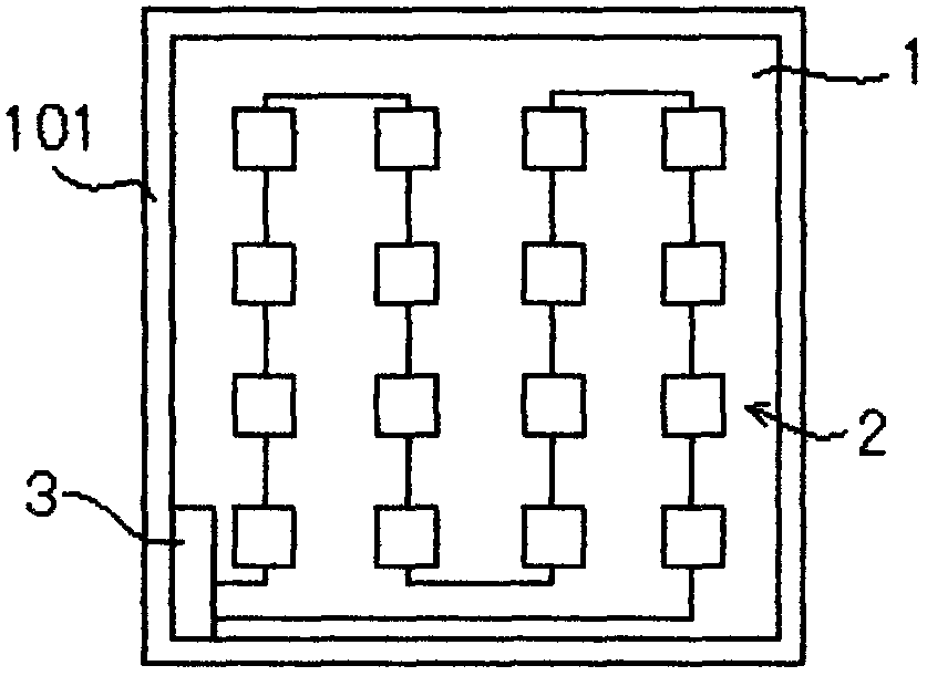
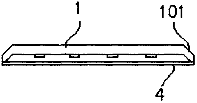
[0034] refer to figure 1 , figure 2 As shown, an LED panel lamp includes a base 1, an LED load circuit 2 connected in series or in parallel, and a lampshade 4 made of a light-transmitting material. The LED load circuit 2 and the lampshade 4 are connected to the base 1. The base 1 is an aluminum plate that doubles as a suspended ceiling, and the surface of the base 1 is coated with an insulating layer. The LED load circuit 2 is printed on the insulating layer, and a power adapter 3 is connected to both ends of the LED load circuit 2 . The LED load circuit 2 is composed of a circuit board and a number of LED light sources directly mounted on the circuit board in an SMT manner.

[0035] In this embodiment, a PC board is selected as the lampshade 4 . In order to fix the lampshade 4 and facilitate installation and disassembly, at least two edges of the base 1 are buckles 101 for fixing the lampshade 4 .

[0036] The power adapter 3 is fixed on the base 1 and placed on the same s...

Embodiment 2

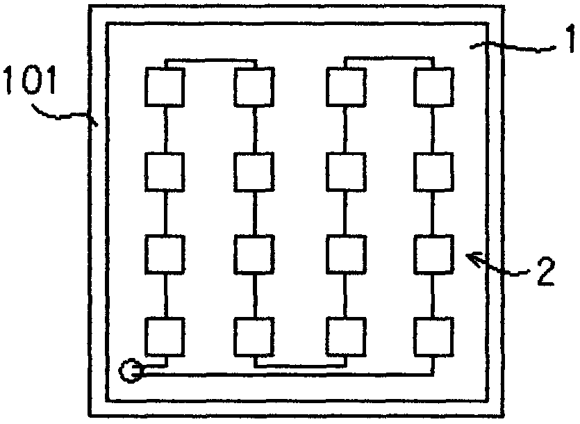
[0038] refer to image 3 , Figure 4 As shown, the rest is the same as that of Embodiment 1, the difference is that the power adapter 3 is fixed on the base 1 and placed on the back of the LED load circuit 2, and the base 1 is provided with an outlet hole so that Connect the LED load circuit 2 with the power adapter 3 .

[0039] A method for manufacturing an LED panel lamp, comprising the following steps:

[0040] Step 1) Printing a circuit board on an aluminum plate;

[0041] Step 2) A plurality of LED light sources are directly mounted on the circuit board in an SMT manner to form a parallel or series LED load circuit;

[0042] Step 3) Cut the aluminum plate according to actual needs to obtain a semi-finished LED panel light;

[0043] Step 4) Stamping the edge of the semi-finished LED panel light into buckles, and the precision of the stamping die is controlled within 0.1mm;

[0044] Step 5) installing a power adapter on the semi-finished LED panel light, the power adap...


PUM

PropertyMeasurementUnit
Thermal conductivityaaaaaaaaaa

Abstract

The invention discloses a light-emitting diode (LED) panel lamp which comprises a base seat, an LED load circuit and a lamp cover, wherein the LED load circuit is formed in a series connection mode or a parallel connection mode, and the lamp cover is made of light-permeable materials. The LED load circuit and the lamp cover are connected on the base seat. The base seat is an aluminum plate which is also used as a suspended ceiling. The LED load circuit is arranged on the surface of the base seat in a printed mode. Two ends of the LED load circuit are connected with a power adaptor. Building materials are combined with the lamp, unessential materials are eliminated, resources are saved, cost is reduced, and meanwhile the weight and the size of the LED panel lamp are reduced. According to integrally forming design, complex manufacture processes are eliminated, and manufacture cost is saved. The base seat with a large area is utilized for assisting heat dissipation, service lives of a power source and a lamp source are prolonged, recycling cost is low, and environment protection is benefited.

Description

technical field [0001] The invention relates to an LED lamp, in particular to an LED panel lamp and a manufacturing method thereof. Background technique [0002] At present, the light sources used for lighting include incandescent lamps and fluorescent lamps. These lamps generally have disadvantages such as not being environmentally friendly (containing heavy metals such as mercury, lead, and arsenic, which are harmful to the environment), high energy consumption, and short life. Therefore, with the global awareness of environmental protection In countries around the world, especially in developed countries and regions, the application of green lighting will become more and more popular, and these lamps will gradually be replaced by green and environmentally friendly light sources. LED lamps are high-efficiency, energy-saving, and long-lasting green and environmentally friendly light sources, which are of great significance for protecting the environment, saving energy, and ...

Claims


Application Information

Patent Timeline
IPC IPC(8): F21S2/00F21V23/00F21V17/10F21V29/00F21Y101/02F21V29/502F21Y115/10
Inventor 赵雨君
Owner FOSHAN AIDIOU PHOTOELECTRIC TECH CO LTD
Learn More