
Thermal cycle type drying equipment

A drying equipment and thermal cycle technology, applied in lighting and heating equipment, drying, dryers, etc., can solve the problems of over-drying or over-humidity, large fuel waste, low heat exchange efficiency, etc., to reduce energy consumption , Reduce the processing cost, the effect of good product quality

Inactive Publication Date: 2013-06-19
洛阳甲天下牡丹园艺有限公司
View PDF5 Cites 1 Cited by
  • Summary
  • Abstract
  • Description
  • Claims
  • Application Information

AI Technical Summary

Problems solved by technology

Traditional drying devices generally use the hot gas generated by the combustion of fuel (such as firewood, coal, gas, etc.) to directly dry fruits and vegetables and other products. Harmful gases such as pollutants, thus affecting the drying quality of agricultural products; there are also isolated smoke pipes, but generally straight smoke pipes are used, and the disadvantages are low heat exchange efficiency and large waste of fuel; ordinary drying devices Generally, the method of one-time loading and one-time taking is adopted. The disadvantages are that the loading and taking-out time period is long, the efficiency is low, fuel and manpower are wasted, and the baked products are not uniform, and it is easy to appear overdry or overhumid.
[0003] This shows that the above-mentioned existing drying device obviously still has inconvenience and defects in structure and use, and needs to be further improved urgently.
In order to solve the above-mentioned problems, the relevant manufacturers have tried their best to find a solution, but no suitable design has been developed for a long time, and the general products do not have a suitable structure to solve the above-mentioned problems. This is obviously related. The problem that the industry is eager to solve

Method used


Image

  • Thermal cycle type drying equipment
  • Thermal cycle type drying equipment

Examples


Embodiment Construction

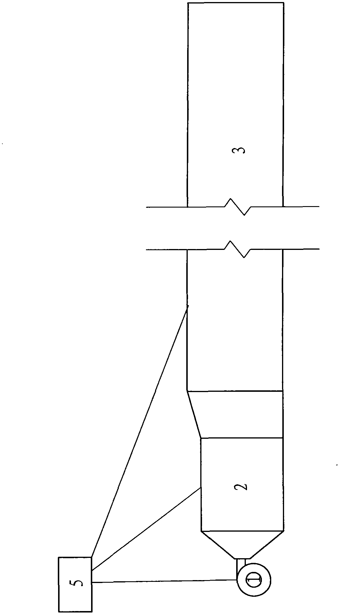
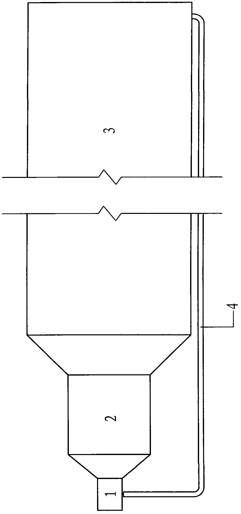
[0019] In order to further explain the technical means and effects of the present invention to achieve the intended purpose of the invention, the specific implementation, structure, characteristics and characteristics of the thermal cycle drying equipment proposed according to the present invention will be described below in conjunction with the accompanying drawings and preferred embodiments. Its effect is described in detail below.

[0020] The aforementioned and other technical contents, features and effects of the present invention will be clearly presented in the following detailed description of preferred embodiments with reference to the drawings. Through the description of the specific implementation, it should be possible to obtain a deeper and more specific understanding of the technical means and effects of the present invention to achieve the intended purpose, but the attached drawings are only for reference and description, not for the purpose of the present invent...


PUM


Abstract

The invention relates to thermal cycle type drying equipment which is composed of an air supply system, a heat supply system, a drying box and an electric cabinet. According to the air supply system, a matched air blower is selected according to the production volume of products and the length of a needed box body, and then an air valve is used for adjusting the volume of air to be appropriate. The air enters the drying box through a heat supply box of the heat supply system and then is sent back to the air blower through an air return pipeline to form a hot air cycle. An appropriate number of heating pipes are mounted in the heat supply box. According to the range of using temperatures, the electric cabinet is used for controlling the heating pipes to be powered on, and heat generated by the heating pipes in the heat supply box is transmitted to the drying box through the air output by the air blower. Sliding rails and multiple material-carrying drying trolleys are arranged in the drying box, and the drying trolleys move forwards along the sliding rails for drying. An electric device and a temperature control device are arranged in the electric cabinet so as to realize automatic adjustment according to the needed temperature. The thermal cycle type drying equipment has the advantages of being high in efficiency, low in energy consumption, high in quality of dried products and the like, and can be widely used for drying flowers, tobacco leaves, medicinal materials, chemical materials and the like.

Description

technical field [0001] The invention relates to a thermal cycle drying equipment used for mass production of flowers, tobacco leaves, medicinal materials, chemical raw materials and other materials requiring temperature-controlled drying. Background technique [0002] Drying technology is of great significance for the deep processing of agricultural products and the increase of added value. Traditional drying devices generally use the hot gas generated by the combustion of fuel (such as firewood, coal, gas, etc.) to directly dry fruits and vegetables and other products. Harmful gases such as pollutants, thus affecting the drying quality of agricultural products; there are also isolated smoke pipes, but generally straight smoke pipes are used, and the disadvantages are low heat exchange efficiency and large waste of fuel; ordinary drying devices Generally, the method of one-time loading and one-time taking is adopted. The disadvantages are that the loading and taking-out tim...

Claims


Application Information

Patent Timeline
IPC IPC(8): F26B9/06F26B21/04F26B25/18
Inventor 任雪玲路畅路买林黄运超李高峰
Owner 洛阳甲天下牡丹园艺有限公司
Learn More