Optic fiber monitoring device for shell component stress

A monitoring device and component technology, applied in the direction of measuring the force of change in optical properties of materials when they are under stress, can solve the problems of limited popularization, expensive monitoring equipment, difficult installation, etc., and achieve a wide range of uses and flexible use methods , The effect of convenient processing and production

Inactive Publication Date: 2013-06-19
XIAN JINHE OPTICAL TECH
View PDF0 Cites 9 Cited by
  • Summary
  • Abstract
  • Description
  • Claims
  • Application Information

AI Technical Summary

Problems solved by technology

Optical fiber sensors are divided into distributed and quasi-distributed. Quasi-distributed sensors include fiber grating sensors and fiber microbend sensors; distributed sensors include Brillouin scattering fiber sensors and fiber Raman sensors. Both of them have anti-electromagnetic Interference, light weight, high precision, long life, high temperature resistance and many other advantages, but its installation is difficult and monitoring equipment is expensive, which limits the promotion and use

Method used


Image

  • Optic fiber monitoring device for shell component stress
  • Optic fiber monitoring device for shell component stress
  • Optic fiber monitoring device for shell component stress

Examples


Embodiment 1

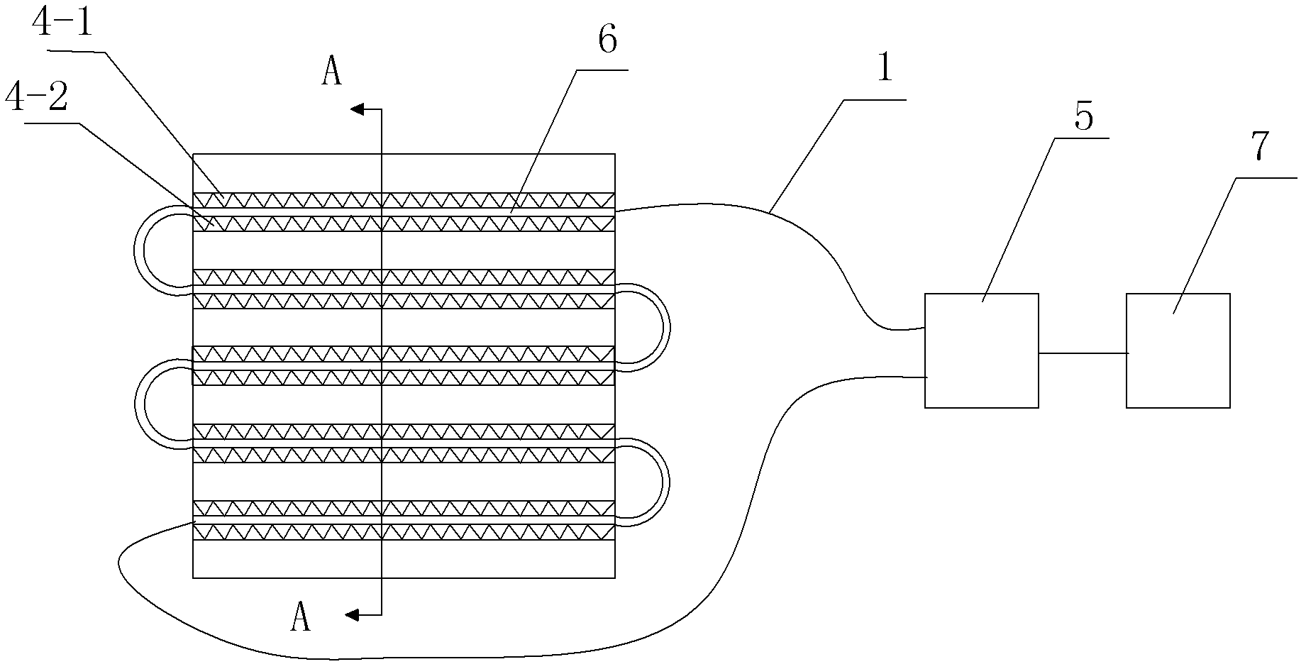
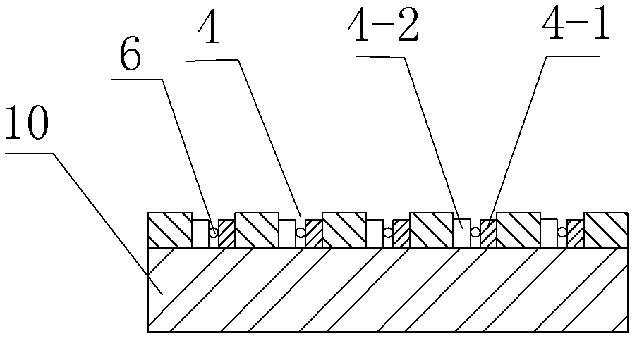
[0028] Such as figure 1 , figure 2 The shown optical fiber monitoring device for shell member stress includes a plurality of parallel first grooves 4 distributed on the shell member 10, and the opposite sides of the first groove 4 have respectively staggered and corresponding A-side deformations. The tooth 4-1 and the B-side deformed tooth 4-2, and the first signal optical fiber 6 is sandwiched between the A-side deformed tooth 4-1 and the B-side deformed tooth 4-2 on the opposite sides of the first groove 4. A signal optical fiber 6 is connected to the test unit 5 through the extension fiber 1 , and the processing unit 7 is connected behind the test unit 5 .

[0029] When the deformation of the shell member 10 widens or narrows the width of the first groove 4, the distance between the deformed teeth on the opposite sides of the first groove 4 will also become larger or smaller, so that the clip The bending curvature of the first signal optical fiber 6 held between the defo...

Embodiment 2

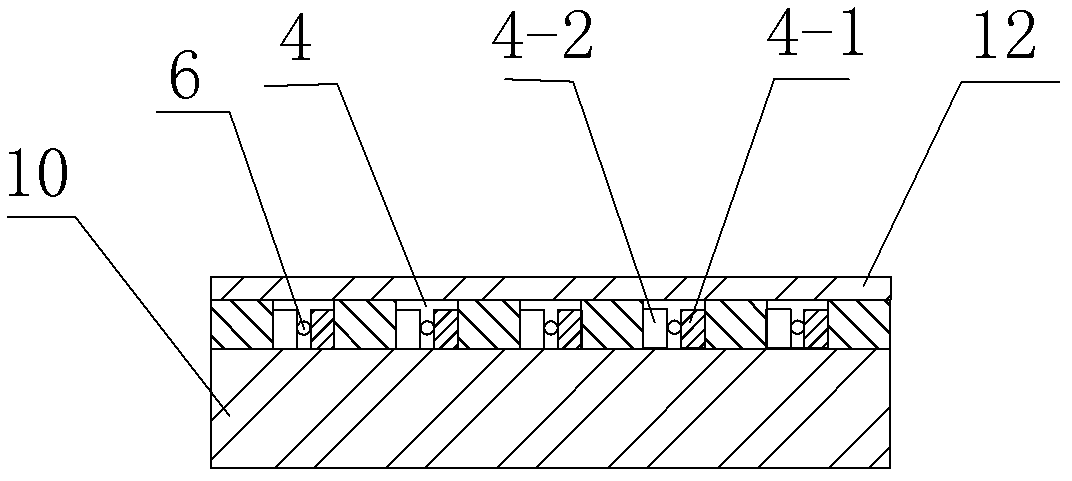
[0038] Such as image 3 As shown, in this embodiment, the difference from Embodiment 1 is that: the first groove 4 is covered with a protective skin 12 to prevent external damage to the first signal optical fiber 6 . In this embodiment, the structures, connections and working principles of other parts are the same as those in Embodiment 1.

Embodiment 3

[0040] Such as Figure 4 , Figure 5 and Figure 6 As shown, in this embodiment, the difference from Embodiment 1 is that the upper and lower surfaces of the shell member 10 are respectively provided with a first groove 4 and a second groove 9, and there are mutual grooves on the opposite sides of the two grooves. The A-side deformed teeth 4-1 and B-side deformed teeth 4-2 are staggered, and the first signal optical fiber 6 and the second signal optical fiber 8 are sandwiched between them, and the first groove 4 and the second groove 9 are at 90 degrees Angle, so that any deformation of the shell member 10 can be monitored.

[0041] In this embodiment, the structures, connections and working principles of other parts are the same as those in Embodiment 1.


PUM


Abstract

The invention discloses an optic fiber monitoring device for shell component stress. The optic fiber monitoring device for the shell component stress comprises a first groove which is formed in a shell component, and A-side deformation teeth and B-side deformation teeth are respectively arranged on two opposite faces in the first groove, wherein the A-side deformation teeth and the B-side deformation teeth correspond to each other in a staggered mode. A first signal optical fiber is clamped between the A-side deformation teeth and the B-side deformation teeth of two opposite sides of the first groove. The first signal optical fiber is connected with a test unit which is connected with a processing unit. Adhesion agents are filled in the first groove. A protective skin is covered on the exterior of the first groove. The optic fiber monitoring device for the shell component stress not only has a good protective effect, but also can detect stress changes when structure is changed, and has distributed monitoring ability.

Description

technical field [0001] The invention relates to an optical fiber stress and strain sensing device, in particular to an optical fiber monitoring device for shell component stress. Background technique [0002] Intelligent structure is a research hotspot at home and abroad today. It is formed by combining sensing elements, driving elements and control systems in matrix materials. It has broad applications in aerospace vehicles, nuclear reactors, ships, submarines, ocean engineering and bridges. Application prospects. Sensing elements in smart structures mainly include electromagnetic, acoustic, chemical, mechanical sensors, biosensors, optical fibers, piezoelectric ceramics, piezoelectric polymers, resistance strain gauges, etc., and optical fiber sensors are a very important direction. Optical fiber sensors are divided into distributed and quasi-distributed. Quasi-distributed sensors include fiber grating sensors and fiber microbend sensors; distributed sensors include Brill...

Claims


Application Information

Patent Timeline
Patent Type & Authority Applications(China)
IPC IPC(8): G01L1/24
Inventor 杜兵
Owner XIAN JINHE OPTICAL TECH
Why Eureka
Try Eureka