
Second generation computed tomography (CT) scanning imaging method

A technology of CT scanning and imaging method, applied in the field of CT scanning, can solve the problems of high utilization rate of scanning rays, difficult to remove ring artifacts, low utilization rate of rays, etc., and achieve good image quality, fast scanning detection speed, scanning Efficiency improvement effect

Active Publication Date: 2014-11-26
CHONGQING UNIV
View PDF3 Cites 0 Cited by
  • Summary
  • Abstract
  • Description
  • Claims
  • Application Information

AI Technical Summary

Problems solved by technology

The third-generation scanning method only needs the relative rotation of the turntable and the fan beam. It is a commonly used scanning method. Its advantages are high utilization of scanning rays and fast scanning speed. The disadvantage is that it is difficult to remove ring artifacts.
The second-generation scanning method requires translational and rotational movements. The advantage of the second-generation scanning method is that it does not require detector consistency correction, and the CT image reconstructed from the scanned data has no ring artifacts, so it is widely used in the industrial field; the second-generation scanning method is widely used in industrial fields; The disadvantage of the scanning method is that the scanning time is long and the ray utilization rate is low
Although the improved scanning method reduces the scanning time, it still collects a lot of redundant data. Therefore, it is necessary to find a more efficient second-generation CT scanning method to improve the detection speed of the workpiece CT scanning, and it is different from the traditional two-generation CT scanning method. Compared with the first-generation scanning method, it must be ensured that the new second-generation scanning method will not cause a decrease in CT image quality

Method used


Image

  • Second generation computed tomography (CT) scanning imaging method
  • Second generation computed tomography (CT) scanning imaging method
  • Second generation computed tomography (CT) scanning imaging method

Examples


Embodiment Construction

[0034] The present invention will be further described below in conjunction with drawings and embodiments.

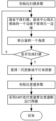
[0035] A second-generation CT scanning imaging method, including a radiation source for emitting radiation, a line array detector for receiving a light source, and a scanning turntable for carrying a workpiece to be measured, the specific steps are as follows:

[0036] 1) Place the workpiece on the scanning turntable, initialize the CT scanning parameters, and set the field of view of the CT scan, which is smaller than the distance from the center of the scanning turntable to the rear collimator;

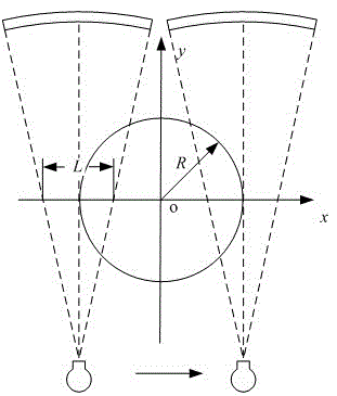
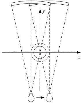
[0037] 2) Calculate the size of the effective field of view, and translate the center line of the ray fan beam to the left of the effective field of view and be tangent to the effective field of view;

[0038] 3) Translate the ray source until the centerline of the ray fan beam moves to the right of the effective field of view and is tangent to the effective field of view, st...


PUM


Abstract

A second generation computed tomography (CT) scanning imaging method comprises a radiation source, a linear array detector and a scanning rotary table. The concrete steps include: (1) initializing CT scanning parameters; (2) carrying out translation scanning on a workpiece; (3) the scanning rotary table rotating by an angle to carry out the translation scanning on the workpiece continuously until the scanning rotary table rotates by a circle; (4) rearranging data obtain through scanning; and (5) by adoption of a search and rescue radar transponder (SART) iterative reconstruction algorithm, rebuilding a CT image. Under the condition that the effect that the quality of the CT image is not reduced is ensured, the speed of the second generation CT scanning imaging method is higher than that of a traditional second generation scanning mode, and scanning efficiency of CT is effectively improved.

Description

technical field [0001] The invention relates to the technical field of CT scanning, in particular to a second-generation CT scanning imaging method. Background technique [0002] Computed Tomography (CT) scanning methods include: first generation scanning method, second generation scanning method (TR), third generation scanning method (RO) and cone beam scanning method, etc. The cone beam scanning method uses an area array detector. The cone beam scanning method has the advantages of large amount of collected data and fast whole-body scanning speed. However, due to the structure of the area array detector, the cone beam scanning method has obvious disadvantages, namely It is impossible to design and manufacture an effective post-collimator, which cannot limit the scattering and crosstalk of X-rays, and the dynamic range is small, especially the acceptable ray energy is low. Generally, only X-rays with lower energy are accepted. For large-size, high-density The artifacts for...

Claims


Application Information

Patent Timeline
Patent Type & Authority Patents(China)
IPC IPC(8): G01N23/04
Inventor 邹永宁王珏罗姗蔡玉芳
Owner CHONGQING UNIV
Learn More