Dual-frequency radio frequency electronic tag

A technology of electronic tags and radio frequency, which is applied in the direction of recording carriers used in machines, instruments, computer components, etc., and can solve the problem of inability to accurately distinguish which card reader is used by multiple card readers, short battery life, and high power consumption of electronic tags. problem, to achieve the effect of reducing design cost, simple circuit, and easy promotion and application

Inactive Publication Date: 2013-06-19
SUZHOU MULAN ELE&TEC
View PDF6 Cites 27 Cited by
  • Summary
  • Abstract
  • Description
  • Claims
  • Application Information

AI Technical Summary

Problems solved by technology

[0003] At present, the electronic tags used in practice are all single-band, and the transmission distance of the electronic tags is usually about 50 meters. The signal range is large, and it is easy to be read by multiple card readers at the same time, and when multiple It is also impossible to accurately distinguish the specific location of the card reader, so it cannot be accurately positioned, which brings a lot of inconvenience to management
At the same time, because the existing electronic tags are in single-band mode, they must constantly send out their own ID numbers, or constantly switch working modes (sending mode and receiving mode) to receive the information sent by the card reader. Information, in this way, the power consumption of the electronic tag will be very high, the battery life will be very short, resulting in a very limited life of the tag

Method used


Image

  • Dual-frequency radio frequency electronic tag
  • Dual-frequency radio frequency electronic tag
  • Dual-frequency radio frequency electronic tag

Examples


Embodiment

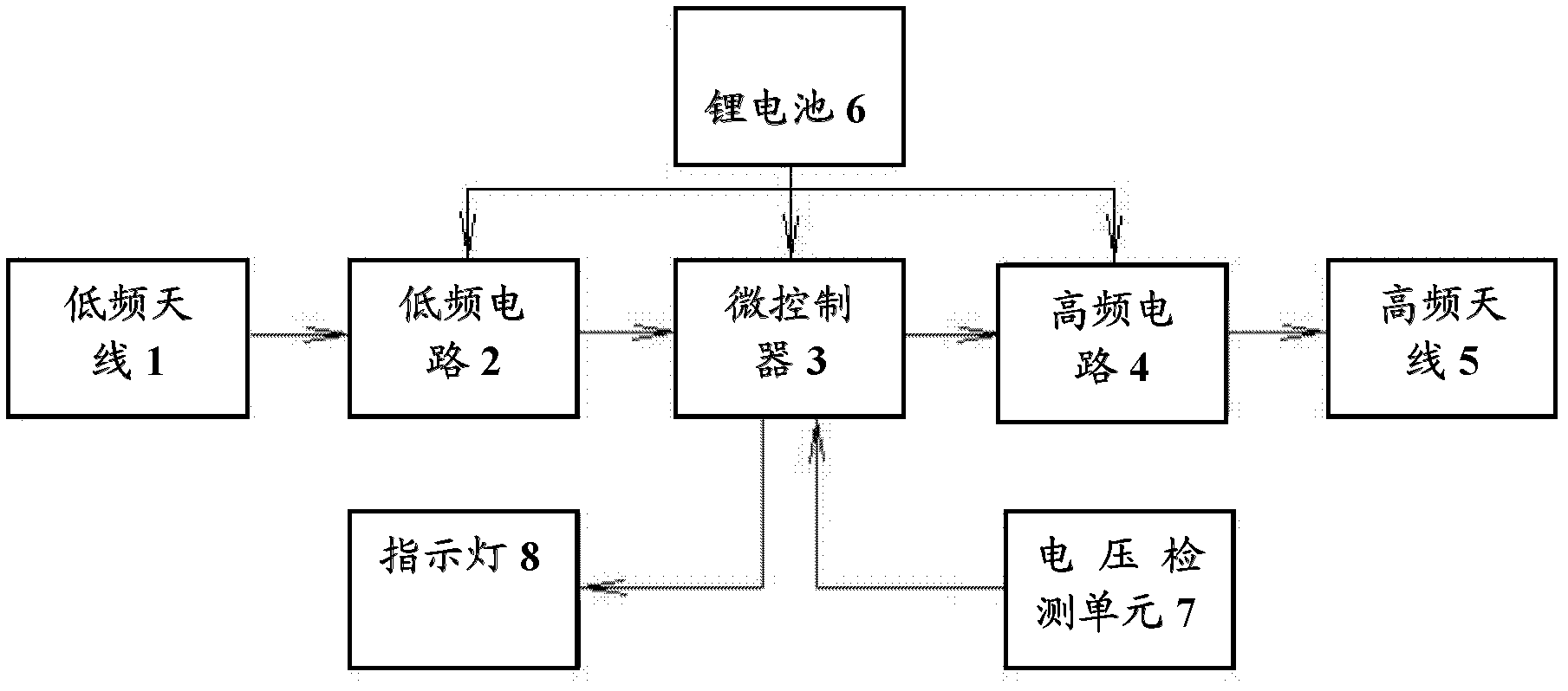
[0036] Embodiment: a dual-frequency radio frequency electronic tag, including:

[0037] The low-frequency antenna 1 is used to receive the low-frequency signal from the activation source and generate an induction signal containing the signal source code. The low-frequency antenna can be a one-dimensional antenna or a 3D antenna. The one-dimensional antenna can achieve a directional effect and reduce other Directional signal interference, 3D antenna is not restricted by direction, it is more convenient to use;

[0038] The low-frequency circuit 2 generates a low-frequency information signal according to the induction signal from the low-frequency antenna 1;

[0039] The high-frequency circuit 4 is used to modulate the intensity identification signal, the signal source code and the electronic tag ID number from the microcontroller 3 into an encoded signal;

[0040] The high-frequency antenna 5 is used to transmit the coded signal into the space through the high-frequency carrier. The hi...


PUM


Abstract

The invention discloses a dual-frequency radio frequency electronic tag which comprises a low frequency antenna used for receiving low frequency signals form an activation source, a low frequency circuit, a high frequency circuit, a high frequency antenna used for sending coded signals to space through high-frequency carrier, and a microcontroller storing identity (ID) numbers of the electronic tag. Programming of the microcontroller comprises the following steps: step one. reading lower frequency information signals and generating intensity identification signals according to intensity of the lower frequency information signals, step two. analyzing and extracting the low frequency information signals and producing signal source codes according to the low frequency information signals, step three. starting timing device interrupt in a time interval, in interrupt status, starting the high frequency circuit, closing the high frequency circuit and opening the low frequency circuit in sequence, step four. quitting the timing device interrupt when time duration achieves the time interval. Distance between the dual-frequency radio frequency electronic tag and a card reader can be measured, accurate positioning is achieved, identification distance is adjustable, and the problem that a plurality of card readers read the same electronic tag at the same time is solved.

Description

technical field [0001] The invention relates to the field of radio frequency identification, in particular to a dual-frequency radio frequency electronic tag. Background technique [0002] In recent years, the Internet of Things is a new technology that people generally pay attention to. As a key technology of the Internet of Things, radio frequency identification technology has developed rapidly. The management of complex environments such as communities, mining areas, and highways has always been highly valued by the relevant state departments, but disputes and even accidents caused by negligent management still occur frequently, causing unnecessary losses of many individuals and the interests of the country. How to strengthen management measures, how to accurately, real-time, and quickly grasp the status of non-residents in residential areas, the distribution and flow of personnel in mining areas, the efficiency of road tolls, and the efficient operation of emergency resc...

Claims


Application Information

Patent Timeline
Patent Type & Authority Applications(China)
IPC IPC(8): G06K19/077
Inventor 白春雨回刚
Owner SUZHOU MULAN ELE&TEC
Why Eureka
Try Eureka