
Mixed random space voltage vector pulse width modulation method and modulator based on field programmable gate array (FPGA)

A space voltage vector, pulse width modulation technology, applied in the field of AC frequency conversion, can solve the problem of cluster spectrum expansion and weakening

Active Publication Date: 2013-06-19
HENAN POLYTECHNIC UNIV
View PDF2 Cites 18 Cited by
  • Summary
  • Abstract
  • Description
  • Claims
  • Application Information

AI Technical Summary

Problems solved by technology

[0025] The purpose of the present invention is to propose a mixed random space voltage vector pulse width modulation method and the equipment using the method, to reduce the problems caused by the deterministic space voltage vector pulse width modulation cluster harmonic spectrum peak, will focus on the modulation frequency Integral and nearby cluster spectrum expansion can be weakened, which can reduce adverse effects such as noise caused by harmonics at lower switching frequencies

Method used


Image

  • Mixed random space voltage vector pulse width modulation method and modulator based on field programmable gate array (FPGA)
  • Mixed random space voltage vector pulse width modulation method and modulator based on field programmable gate array (FPGA)
  • Mixed random space voltage vector pulse width modulation method and modulator based on field programmable gate array (FPGA)

Examples


Embodiment Construction

[0104] In order to make the object, technical solution and beneficial effect of the present invention clearer, the present invention will be further described in detail through the following embodiments.

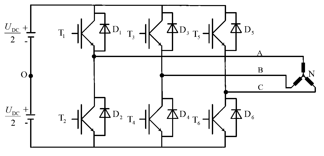
[0105]The invention provides a mixed random space voltage vector pulse width modulation method and a modulator based on FPGA, the structure of the inverter is as follows figure 1 shown. The modulator provided by the present invention can be installed between the controller and the isolation drive circuit of the frequency conversion speed regulation system, and it can also be integrated with the controller in an FPGA, such as Figure 7 shown.

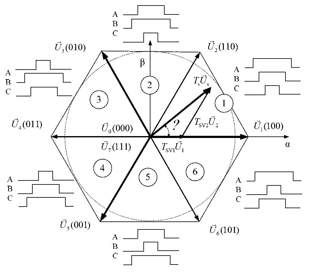
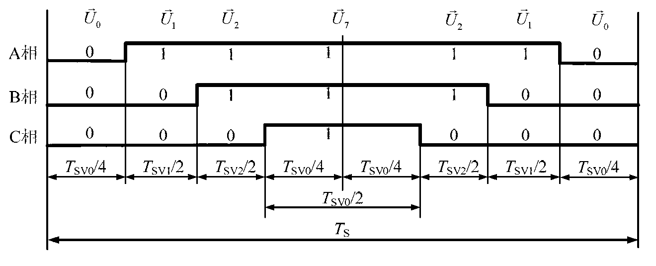
[0106] The implementation of the present invention first needs to calculate the action time of two adjacent basic voltage vectors and zero voltage vectors according to the command voltage vector output by the controller, and then calculate the moment of pulse jumping. The implementation steps are as follows Figure 6 As shown, the de...


PUM


Abstract

The invention relates to an FPGA (mixed random space voltage vector pulse width modulation method) and a modulator based on a field programmable gate array. According to the method, action time and pulse and pulse positioning of a basic voltage sector are controlled by two random variables, one of the two random variables is used for controlling the action time of the basic voltage vector by controlling distribution proportion of action time of two zero vectors, and the other random variable is used for performing pulse positioning by controlling the position of the widest high-level pulse. The modulator comprises a period register, a dead zone register, two groups of hop time registers, a counting and initial value reloading circuit, a register switching circuit and a pulse generation circuit, and an asymmetrical control pulse is generated through alternative comparison of the two groups of hop time registers. By the modulation method and the modulator, mechanical vibration, audio-frequency noise, electromagnetic radiation and the like due to a large peak value of a discrete set cluster spectrum are obviously avoided on the premise that fundamental wave voltage and switching frequency do not change.

Description

technical field [0001] The invention belongs to the technical field of AC frequency conversion, and in particular relates to a mixed random space voltage vector pulse width modulation method capable of reducing harmonic peaks and an FPGA-based modulator. Background technique [0002] Such as figure 1 The inverter shown has the advantages of simple structure and convenient implementation, and is widely used in occasions such as electric vehicle drive and other frequency conversion speed regulation. The pulse width modulation (PWM) used is based on the principle of "volt-second balance", and the voltage pulse with a continuously changing duty cycle is equivalent to the command voltage according to the time average. The essence of the modulation strategy is to use a certain algorithm to calculate the high and low level transition times of the 6 switching signals required by the inverter according to the command voltage, use the logic circuit to generate 6 pulse signals, and th...

Claims


Application Information

Patent Timeline
Patent Type & Authority Applications(China)
IPC IPC(8): H02M1/12
Inventor 陈国强康件丽黄俊杰张明军孙付伟赵俊伟
Owner HENAN POLYTECHNIC UNIV
Learn More