Direct drive type stroke control pressurizing type hydraulic machine of oil-less pump alternating current servo motor

A technology of AC servo motor and stroke control, which is applied in the driving device of stamping machine, forging press, press machine, etc., to achieve the effects of high positioning accuracy, flexible and adjustable working characteristics, and improved transmission efficiency

Inactive Publication Date: 2013-06-26
XI AN JIAOTONG UNIV
View PDF5 Cites 9 Cited by
  • Summary
  • Abstract
  • Description
  • Claims
  • Application Information

AI Technical Summary

Problems solved by technology

Therefore, rapid forging hydraulic presses have appeared, that is, hydraulic servo presses using AC servo motors, such as WIDEMANN and W.A.WHITNEY in the United States, TRUMPF and NIXOORF DARADORN in West Germany, AIDA and NISSHINBO in Japan, and RASKIN in Switzerland. Manufactured hydraulic servo presses, turret punch presses or multi-station mechanical presses, the speed and flexible control of the existing hydraulic servo presses are mainly reflected in the control of the auxiliary parts of the machine tool such as the T-axis, worktable, automatic feeding, and air circuits. In fact, there are few direct and precise improvements to the transmission mechanism that significantly affects the working function of the press and the quality of the processed product.

Method used


Image

  • Direct drive type stroke control pressurizing type hydraulic machine of oil-less pump alternating current servo motor
  • Direct drive type stroke control pressurizing type hydraulic machine of oil-less pump alternating current servo motor
  • Direct drive type stroke control pressurizing type hydraulic machine of oil-less pump alternating current servo motor

Examples


Embodiment Construction

[0016] The present invention will be described in further detail below in conjunction with the accompanying drawings and embodiments.

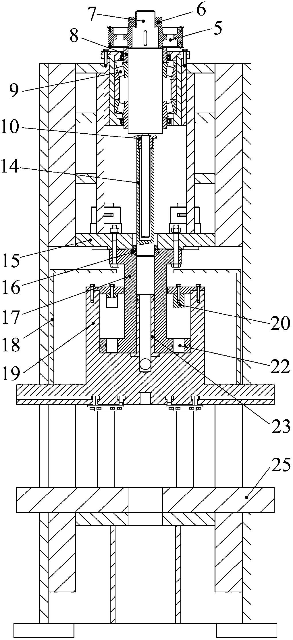
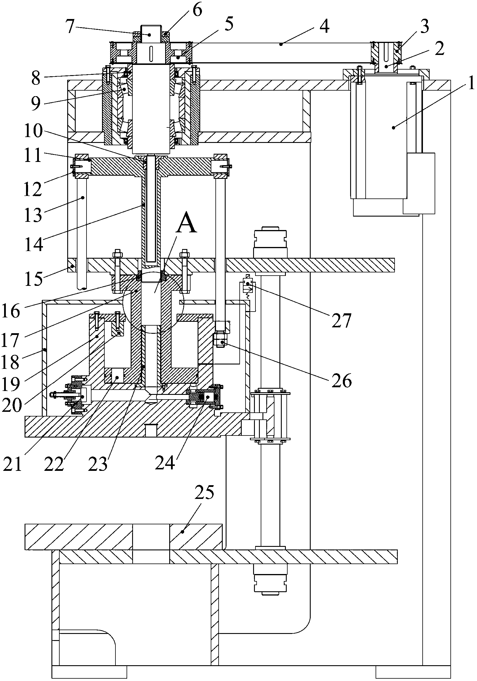
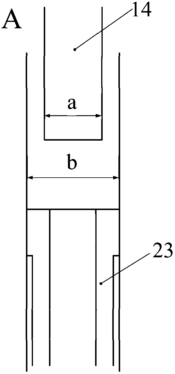
[0017] Such as Figures 1 to 2As shown, an oil-pump AC servo motor direct-drive stroke control pressurized hydraulic press includes an AC servo motor 1 and a small pulley 3 connected to its rotating shaft 2. The small pulley 3 is connected to a large belt through a toothed belt 4 The pulley 5 and the large pulley 5 are integrated with the ball screw 7 through two large round nuts 6. The large pulley 5 can drive the ball screw 7 to rotate together. The lower end of the large pulley 5 is supported on the bearing 9 through the support sleeve 8. The large pulley 5 is used as an inertia wheel, the ball screw 7 is equipped with a screw nut 10, the screw nut 10 and the large piston 14 are radially matched and connected as one, and the two ends of the large piston 14 are symmetrically connected with a pull rod 13, and the pull rod 13 passes through th...


PUM


Abstract

The invention discloses a direct drive type stroke control pressurizing type hydraulic machine of an oil-less pump alternating current servo motor. The direct drive type stroke control pressurizing type hydraulic machine of the oil-less pump alternating current servo motor uses a ball screw transmission mechanism and a servo drive manner of an alternating current servo motor. The flying wheel transmission theory of a spiral pressure machine is applied to the hydraulic machine so as to achieve that the screw ball rotates to drive a screw nut to downwards move in a high speed. Fast downward movement and returning of a sliding block of the hydraulic machine are performed as the alternating current servo motor directly drives the ball screw. A main and vice composite pressurizing cylinder is used for achieving low-speed force adding pressing. Meanwhile, stamping drive force is reduced. A main cylinder body is integrated with the sliding block. Liquid can be rapidly filled and discharged as a small piston and a small piston cavity rapidly move upwards and downwards. A double-pull-rod structure is movably connected with the main cylinder body to achieve flexible forging and pressing and high-speed stroke returning movement of the sliding block. The transmission efficiency of the hydraulic machine is greatly improved, positioning precision of the sliding block is high, fast descending speed and stoke returning speed can reach 700mm/s, the technical requirements of low-speed forging and pressing and high-speed idle stroke are met, working characteristics of the pressure machine can be flexibly adjusted, energy is saved and consumption is reduced.

Description

technical field [0001] The invention belongs to the technical field of forging press equipment manufacturing, and in particular relates to an oil-pump AC servo motor direct-drive type stroke control supercharged hydraulic press. Background technique [0002] The hydraulic press is a device that uses hydraulic transmission technology for pressure processing, and is one of the most widely used equipment in product molding production. The traditional hydraulic press generally includes an oil pump and a hydraulic cylinder transmission system. Its main disadvantage is that the speed is low, and the speed of the quick drop and return is only 100-200mm / s. In recent years, major industrialized countries in the world are trying to increase the speed of hydraulic presses in order to increase productivity. Improving the working speed of the hydraulic press means shortening the working cycle time of the hydraulic press. The key to reducing the working cycle time of the hydraulic press ...

Claims


Application Information

Patent Timeline
Patent Type & Authority Applications(China)
IPC IPC(8): B21J9/18B30B1/23
Inventor 范淑琴赵升吨张琦李旭陈超
Owner XI AN JIAOTONG UNIV
Why Eureka
Try Eureka