Electrolytic copper foil equipment fly cutter device

A technology of electrolytic copper foil and equipment, which is applied in the field of anode flying knife device of electrolytic copper foil equipment, can solve the problems of high processing cost, waste of energy, large volume, etc., and achieve the effects of convenient operation and maintenance, guaranteed continuity, and small volume

Inactive Publication Date: 2013-06-26
XIAN AEROSPACE YUANZHENG FLUID CONTROL
3 Cites 3 Cited by

AI-Extracted Technical Summary

Problems solved by technology

[0009] In order to solve the technical problems of the existing electrolytic copper foil equipment flying knife device with large volum...

Abstract

The invention relates to an electrolytic copper foil equipment fly cutter device which comprises a control mechanism, a frequency change motor, a transmission assembly and a cutter rod assembly. The transmission assembly comprises a main driving wheel, a feed chain wheel, a rotary chain wheel, a rotary barrel, a rolling screw and a rolling nut. The electrolytic copper foil equipment fly cutter device solves the technical problems that an existing electrolytic copper foil equipment fly cutter device is large in size, high in processing cost and capable of wasting energy. The electrolytic copper foil equipment fly cutter device has the advantages of saving energy, light in structure, convenient to install and long in service life.

Application Domain

Stock shearing machinesDriving apparatus +1

Technology Topic

Copper foilElectrical and Electronics engineering +2

Image

  • Electrolytic copper foil equipment fly cutter device
  • Electrolytic copper foil equipment fly cutter device
  • Electrolytic copper foil equipment fly cutter device

Examples

  • Experimental program(1)

Example Embodiment

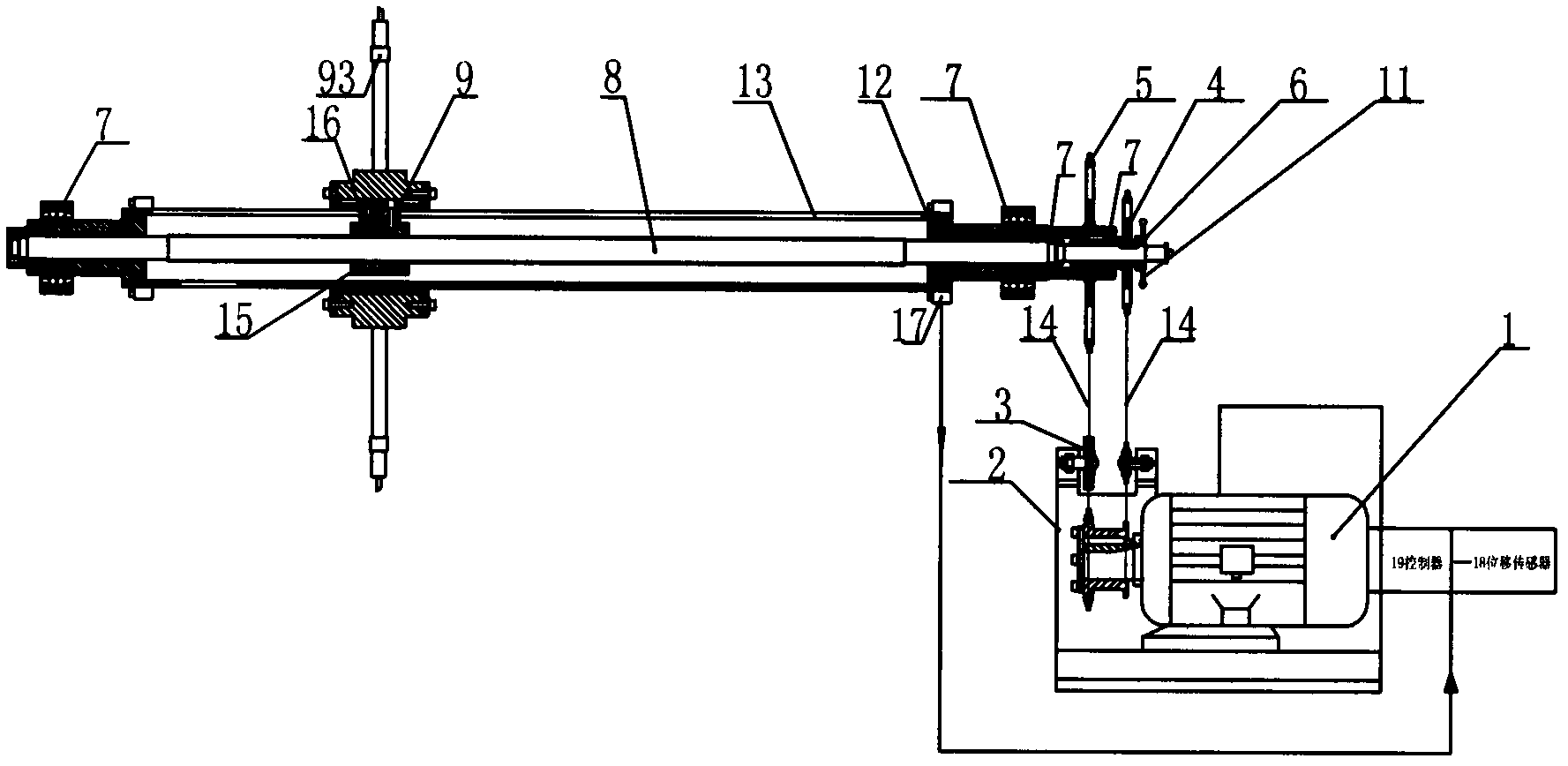
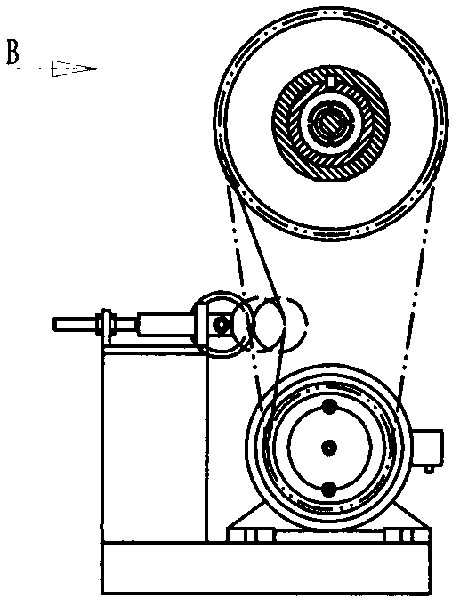
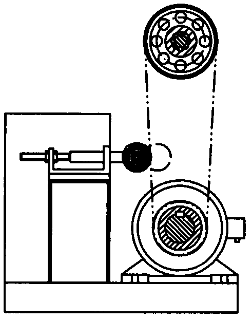
[0026] Such as figure 1 , figure 2 , image 3 Shown is a schematic structural diagram of the flying knife device of the electrolytic copper foil equipment of the present invention, including a power source, a transmission assembly and a knife bar assembly. The power source is a variable frequency motor 1, and the main driving wheel 2 is arranged at the power output end of the variable frequency motor 1; the transmission assembly It includes two main driving wheels 2, a feed sprocket 4, a rotating sprocket 5, a rotating drum 12, a rolling screw 8, and a rolling nut 15. The rotating drum 12 is a hollow long cylinder with a feed slot 13 in the axial direction, Its two ends are respectively supported by bearings; the rolling screw 8 is coaxially arranged in the rotating cylinder 12 and the two ends are respectively rotatably connected with the rotating cylinder 12 through a self-aligning bearing 7; the rolling nut 15 can rotate under the driving of the rolling screw 8 The cylinder 12 moves along the axial direction of the rolling screw 8; two main driving wheels 2 are fixed side by side on the output shaft of the power source; the feed sprocket 4 and the rotating sprocket 5 pass through the transmission chain 14 and a main driving wheel 2 respectively The feed sprocket 4 and the rolling screw 8 are coaxially connected by the clutch 6; the rotating sprocket 5 is rotatably connected with the feed sprocket 4 through the self-aligning bearing 7 and is firmly connected to the rotating drum 12; the main driving wheel 2 and the feed A tension sprocket 3 is provided between the feed sprocket 4 and a tension sprocket 3 is provided between the main driving wheel 2 and the rotating sprocket 5.
[0027] An independent variable frequency motor is used, and two independent sprockets are used to rotate respectively. The two-stage sprockets use the speed difference ratio to achieve transmission difference, cleverly realize the low-speed rotation and feed movement of the equipment, which is beneficial to the main parts of the equipment. Stable operation, extending the service life of the equipment.
[0028] The flying knife device of the electrolytic copper foil equipment also includes a control mechanism, which includes a travel switch and a displacement sensor arranged between the rotating drum and the rolling screw. The control mechanism adopts the travel switch and displacement sensor positioning, which effectively avoids the occurrence of safety accidents.
[0029] Such as Figure 4 , Figure 5 Shown is a schematic diagram of the structure of the cutter bar assembly of the present invention, including a base 91 sleeved outside the rotating cylinder, a cutter bar 92 fixed vertically on the base, a cutter 94 arranged at the outer end of the cutter bar, a base 91 and a rolling nut 15 through the guide key 16 fixed connection. The cutting blade 94 is connected to the tool bar 92 through a differential nut 93, and the motion is transmitted by the differential thread, which can realize accurate feeding and fine adjustment.
[0030] Such as Image 6 , Figure 7 Shown is the schematic diagram of the clutch disengaged structure of the present invention. After the clutch is disconnected online, during the movement of the entire mechanism, the flying knife assembly only moves in a circular motion without feeding, which is convenient for workers to operate and avoids parking And waste a lot of time. There is no need to stop the machine, just after the clutch is disengaged, the rotating parts and the feeding parts can be automatically separated, which saves a lot of time, improves the working efficiency of the equipment, and creates higher economic benefits.
[0031] The working process of the present invention:
[0032] The present invention is a flying knife device for electrolytic copper foil equipment. Through the frequency conversion motor and the main drive sprocket 2 through the two transmission chains 14 through the tension sprocket 3 to adjust the sprocket tightness, the power is transmitted to the feeding sprocket 4 and rotating Sprocket 5. The feed sprocket 4 drives the rolling screw 8 to move, and the rotating sprocket drives the rotating drum 12 to rotate. The rolling nut 15 can move along the axial direction of the rolling screw 8 in the rotating drum 12 under the driving of the rolling screw 8; The tool bar assembly 9 is driven to rotate and feed at the same time. The amount of cutting tool is adjusted by the differential nut 10 to complete the entire cutting process. When manual operation needs to be switched, only the clutch 6 needs to be separated from the feed sprocket 4, and then Manual operation can be achieved by turning the handwheel.

PUM

no PUM

Description & Claims & Application Information

We can also present the details of the Description, Claims and Application information to help users get a comprehensive understanding of the technical details of the patent, such as background art, summary of invention, brief description of drawings, description of embodiments, and other original content. On the other hand, users can also determine the specific scope of protection of the technology through the list of claims; as well as understand the changes in the life cycle of the technology with the presentation of the patent timeline. Login to view more.

Similar technology patents

Method used for simulating all air-air conditioning system and device thereof

InactiveCN104764166AEnergy savingThe science of regulation
Owner:SUZHOU UNIV OF SCI & TECH

Multistage-series stepped natural-type artificial wetland and construction method

InactiveCN103214148AEnergy savingGood for water purification
Owner:SHANDONG ANALYSIS & TEST CENT

Forced circulation continuous crystallization system with mechanical vapor recompression function

InactiveCN101874938AEnergy savingNo need for condensing equipment
Owner:JIANGSU LEKE THERMAL ENG EQUIP +1

Method for preparing carbonized titanium powder by vacuum carbothermal reduction

InactiveCN101734660AEnergy savingNot easily oxidized
Owner:KUNMING UNIV OF SCI & TECH

Multifunctional screw turning device

Owner:嘉善县晓海金属制品厂(普通合伙)

Classification and recommendation of technical efficacy words

  • flexible structure
  • Energy saving

Distributed multi-sensor mobile robot system

ActiveCN101612733AImprove computing powerflexible structure
Owner:INST OF AUTOMATION CHINESE ACAD OF SCI

Novel pneumatic manipulator

ActiveCN104002304Aflexible structureImprove working precision
Owner:KUNMING UNIV OF SCI & TECH

Large-span waveband dual-band controllable relativistic backward-wave oscillator

ActiveCN105869972Aflexible structure
Owner:INST OF APPLIED ELECTRONICS CHINA ACAD OF ENG PHYSICS

Data center and cooling system thereof

Owner:HONGFUJIN PRECISION ELECTRONICS (TIANJIN) CO LTD

Photovoltaic cleaning robot

InactiveCN104984942AEnergy savingeasy to use
Owner:上海联星股权投资管理有限公司
Why Eureka
Try Eureka