
A semi-automatic threading machine

A looping machine and semi-automatic technology, which is applied to the looping machine connecting knitted fabrics, sewing machine components, sewing machine control devices, etc., can solve the problems of workers' high vision requirements, error-proneness, and increased worker burden, etc., and meet the vision requirements Not high, the effect of reducing labor intensity

Active Publication Date: 2015-08-05
山东中曾康弘硅胶科技有限公司
View PDF4 Cites 0 Cited by
  • Summary
  • Abstract
  • Description
  • Claims
  • Application Information

AI Technical Summary

Problems solved by technology

The looping machine in the prior art is fixed on a fixed base and the radius of the dial is relatively long. When the worker puts the sweater on the dial, he needs to move back and forth relative to the dial. Increased the burden on the workers; moreover, because the ring gear is too dense and too thin, the requirements for the eyesight of the workers are very high, and it is difficult and error-prone for the workers to put the sweater on the dial

Method used

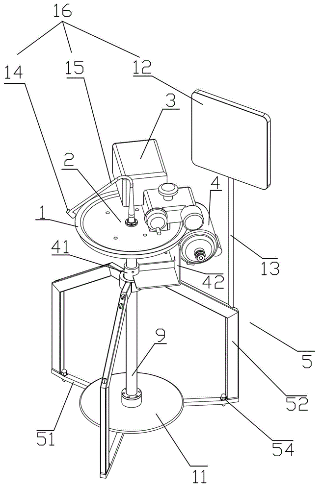
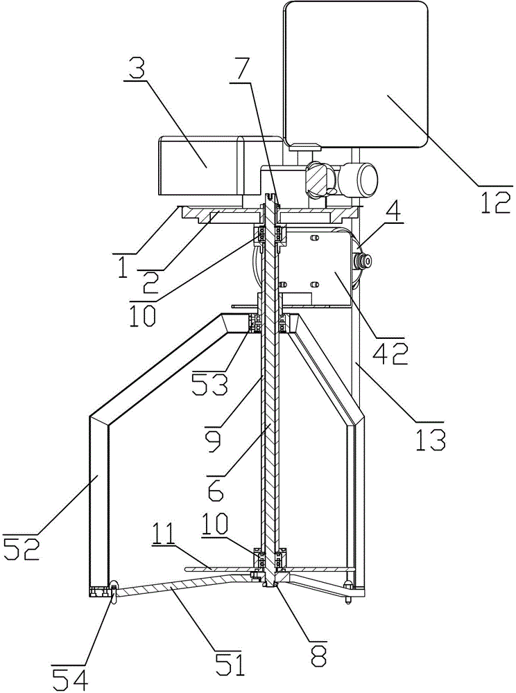
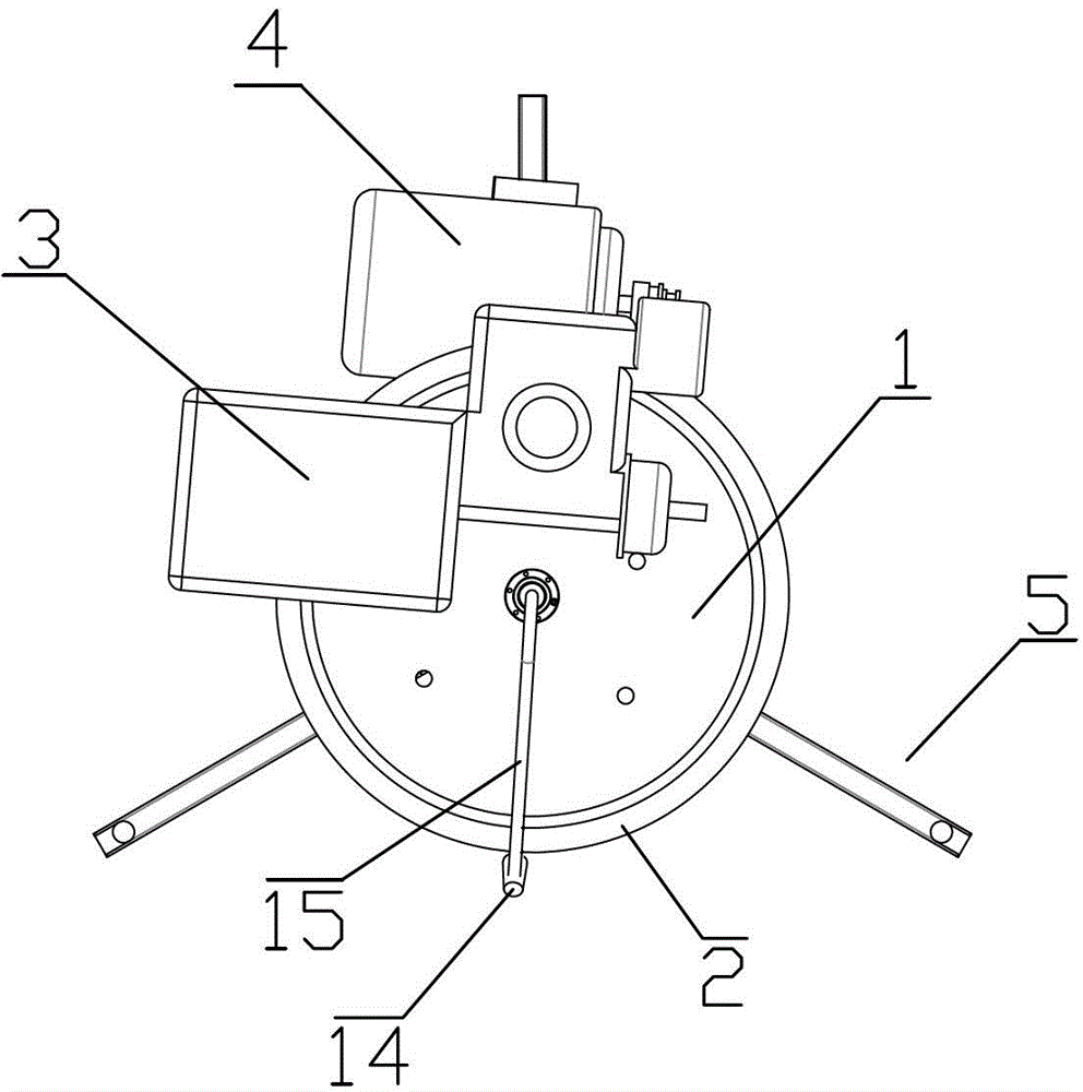

Image

  • A semi-automatic threading machine
  • A semi-automatic threading machine
  • A semi-automatic threading machine

Examples


Embodiment Construction

[0018] Such as figure 1 , 2 3. What the present invention discloses as shown in 3 is a kind of semi-automatic threading machine, and it comprises dial 1, and is fixed on the dial 1 and is arranged on the machine head 3 that is connected with ring gear 2 on the peripheral edge of dial 1, and this machine head 3 Driven by the main motor 4, the dial 1 is movably connected with the ring gear 2; it also includes a tripod support frame 5 and a fixed shaft 6 that is movably connected to the tripod support frame 5 in the axial direction, and one end of the fixed shaft 6 passes through a lock nut 7 It is fixedly connected to the lower end surface of the dial 1, and the other end is fixedly connected to the upper end surface of the rotating disk 11 through a fixed nut 8. The fixed shaft 6 is wrapped with a transition shaft 9, and the transition shaft 9 is fixed through the fixed shaft 9 at both ends of the fixed shaft 6. The bearing 10 limits the fixed shaft 6 in the transition shaft 9...


PUM


Abstract

The invention belongs to the field of garment machinery, and particularly relates to a semi-automatic linking machine. The semi-automatic linking machine comprises a needle dial and a handpiece, wherein the handpiece is fixed on the needle dial and is connected with a tooth ring which is arranged on the periphery of the needle dial in a matched mode. The handpiece is driven through a main motor, and the needle dial is connected with the tooth ring in a movable mode. The semi-automatic linking machine further comprises a tripod support and a fixed shaft, wherein the fixed shaft is connected to the tripod support in the axial direction in a movable mode, one end of the fixed shaft is fixedly connected to the lower end face of the needle dial through a fastening nut, the other end of the fixed shaft is fixedly connected to the upper end face of a rotary disc through a fixing nut, the outer portion of the fixed shaft is wrapped with a transition shaft, and the transition shaft enables the fixed shaft to be limited inside the transition shaft through fixing bearings at two ends of the fixed shaft. The semi-automatic linking machine can largely lessen labor burdens of workers and lower vision demands to operation workers.

Description

technical field [0001] The invention belongs to the field of garment machinery, and in particular relates to a semi-automatic sewing machine. Background technique [0002] The looping machine is a machine that uses sutures to sew the loops of sweaters. With the help of the looping machine, the looping of sweaters can be completed efficiently and quickly. The looping machine of the prior art includes a dial, and a machine head fixed on the dial, and the nose cooperates with a ring gear arranged on the periphery of the dial to complete the stitching of the sleeve of the sweater. The looping machine in the prior art is fixed on a fixed base and the radius of the dial is relatively long. When the worker puts the sweater on the dial, he needs to move back and forth relative to the dial. Increased the burden on the workman; moreover, because the ring gear is too dense and too thin, so the workman's eyesight requirements are very high, and the workman is difficult and error-prone ...

Claims


Application Information

Patent Timeline
Patent Type & Authority Patents(China)
IPC IPC(8): D05B7/00D05B69/06
Inventor 王虎伍国新傅珠荣王伟民
Owner 山东中曾康弘硅胶科技有限公司
Learn More