Non-contact LED junction temperature measurement method and device

A test method, non-contact technology, applied in measuring devices, thermometers, measuring heat, etc., can solve problems such as high cost, inability to be widely used, and difficulty in realization

Inactive Publication Date: 2013-06-26
CHINA JILIANG UNIV
View PDF2 Cites 13 Cited by
  • Summary
  • Abstract
  • Description
  • Claims
  • Application Information

AI Technical Summary

Problems solved by technology

The first two are contact test methods, but after the LED is integrated, due to the limitations of the system casing, waterproof insulation materials, etc., usually the pins of the LED cannot be touched, so these two methods are limited; the latter three methods are difficult to implement , high cost and cannot be widely used

Method used


Image

  • Non-contact LED junction temperature measurement method and device
  • Non-contact LED junction temperature measurement method and device

Examples


Embodiment Construction

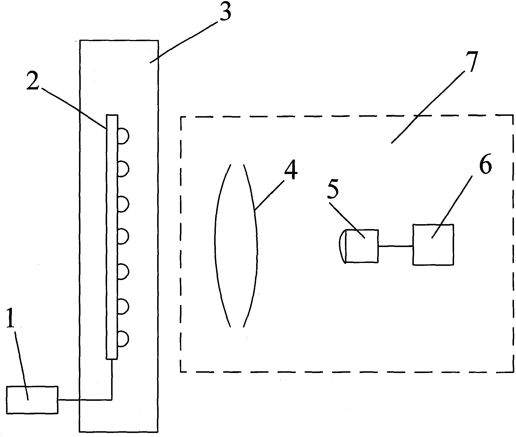
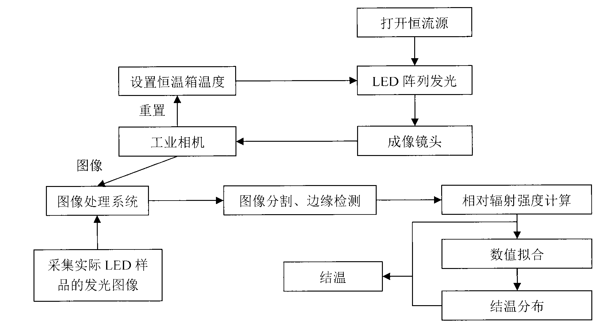
[0017] figure 1 , figure 2 Among them, the non-contact LED junction temperature test method: put the LED array 2 in the thermostat 3 with an initial temperature of 20°C for 20 minutes and stabilize it for 20 minutes. At this time, the temperature of the thermostat 3 is regarded as the initial junction temperature of the LED array 2. Turn on the constant current source 1 to drive the LED array 2 to emit light, collect the image of the LED array 2 under the temperature condition through the CMOS industrial camera 5 carrying the imaging lens 4, and transmit the image to the PC, and use the image processing system 6 to pair the collected The image is segmented and edge detected, and the area where each LED is located in the LED array 2 image is segmented, so that the size of each LED area is equal, and then the average value of the gray value of each LED area is calculated as the corresponding single LED For the relative radiation intensity, the relative radiation intensity of e...


PUM


Abstract

The invention discloses non-contact LED junction temperature measurement method and device. The method includes: placing an LED array in a thermostatic tank, using a constant current source to drive the LED array to emit light, regulating set temperature of the thermostatic tank, using a CMOS (complementary metal-oxide-semiconductor) industrial camera with an imaging lens to capture images of the LED array at different set temperatures, transmitting the images to a PC (personal computer), using LabVIEW software to process the captured images and calculate relative radiation intensity to obtain the LED relative radiation intensity corresponding to each temperature, and fitting and calibrating to obtain distribution relation between LED junction temperature and the relative radiation intensity. The non-contact LED junction temperature measurement device applying the relation comprises the CMOS industrial camera with the imaging lens and an image processing system. The image processing system processes the captured images of an LED and calibrates the relation, and the LED junction temperature can be obtained. The measurement method and device are fast, accurate, simple and handy and need no contact with pins of the LED.

Description

technical field [0001] The invention relates to an LED junction temperature testing method and device, in particular to a non-contact LED junction temperature testing method and device. Background technique [0002] Due to the advantages of energy saving, environmental protection, high brightness, long life, small size, and low cost, LEDs have been widely used in various lighting fields. The P-N junction temperature of the LED is too high, resulting in a decrease in the internal quantum efficiency, which ultimately reduces the luminous efficiency and affects the service life of the LED. In order to study and solve the adverse effects caused by excessively high LED junction temperature, fast and accurate measurement of LED junction temperature has become the focus of researchers. At present, the junction temperature testing methods mainly include forward voltage method, thermal resistance method, peak wavelength method, white-blue ratio method and infrared camera method. Th...

Claims


Application Information

Patent Timeline
Patent Type & Authority Applications(China)
IPC IPC(8): G01K11/00
Inventor 梁培杨松涛徐定科周燕飞黄杰王乐
Owner CHINA JILIANG UNIV
Why Eureka
Try Eureka