Detection apparatus, power receiving apparatus, non-contact power transmission system and detection method

A detection device and power receiving technology, applied in the direction of measurement device, electromagnetic wave system, radio wave measurement system, etc., can solve the problems of difficult to determine the change of parameters, difficult to determine the loss of eddy current, etc., and achieve the effect of improving the accuracy of detection

Active Publication Date: 2013-06-26
SONY CORP
View PDF9 Cites 31 Cited by
  • Summary
  • Abstract
  • Description
  • Claims
  • Application Information

AI Technical Summary

Problems solved by technology

In this case, it is difficult to determine whether the change in parameters is caused by the influence of metal shells, etc., or by the presence of metal foreign objects
For example, in the case of the technique disclosed in Patent Document 2, it is difficult to determine whether the eddy current loss is caused by the metal

Method used


Image

  • Detection apparatus, power receiving apparatus, non-contact power transmission system and detection method
  • Detection apparatus, power receiving apparatus, non-contact power transmission system and detection method
  • Detection apparatus, power receiving apparatus, non-contact power transmission system and detection method

Examples


no. 1 example

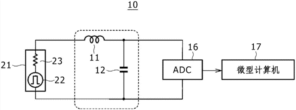
[0031] 2. First embodiment (signal source: example using a pulse generator)

[0032] 3. Second Embodiment (Detection Circuit: Representative Application to Power Receiving Device)

[0033] 4. The third embodiment (detection circuit: an example using an envelope-line detection circuit)

no. 4 example

[0034] 5. Fourth Embodiment (Q Factor Measurement: Representative Q Factor Measurement Using Vibration Quantity)

[0035]6. The fifth embodiment (Q factor measurement: based on the voltage V within a predetermined range 2 A representative Q-factor measurement of the

no. 6 example

[0036] 7. The sixth embodiment (Q factor measurement: even if the voltage V 2 Not within predetermined range, based on time-limited representative Q-factor measurements)

[0037] 8. Other

[0038] 1 Introduction

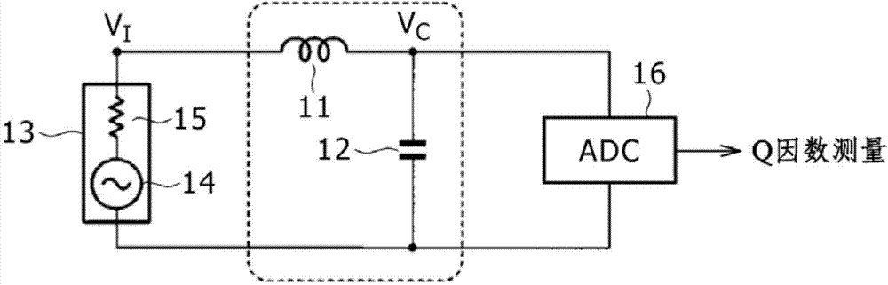
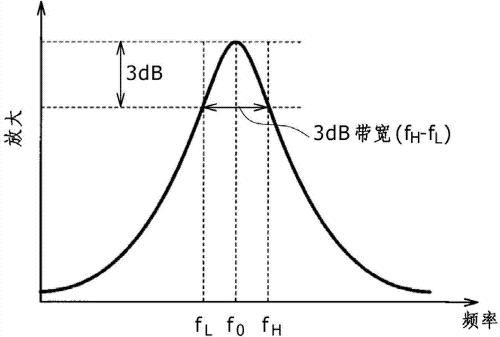
[0039] Detection of metallic foreign objects by measuring the Q factor

[0040] In order to detect with high precision the presence of metallic foreign matter between the power transmitting side and the power receiving side, a method has been conceived that determines whether or not the metallic foreign matter is located between the power receiving side and the power receiving side based on the measured Q factor (quality factor) of the circuit. A position close to a coil included in the resonance circuit on the power transmission side, which is a coil magnetically coupled to an external component on the power transmission side. Since the Q factor of the circuit decreases as the metal foreign matter approaches the resonant circuit, the presence or absence of the me...


PUM


Abstract

The invention relates to a detection apparatus, a power receiving apparatus, a non-contact power transmission system and a detection method. The detection apparatus includes: a resonant circuit provided with a Q-factor measurement coil and one or more capacitors to serve as a circuit for receiving pulses; a response-waveform detecting section configured to detect the waveform of a response output by the resonant circuit in response to the pulses; and a Q-factor measuring section configured to measure a Q factor of the resonant circuit from the response waveform detected by the response-waveform detecting section. It is possible to increase the precision of detection of a metallic foreign substance existing between a power transmitting side and a power receiving side.

Description

[0001] Cross References to Related Applications [0002] The present application contains subject matter related to the disclosure of Japanese Priority Patent Application JP 2011-280059 filed in the Japan Patent Office on Dec. 21, 2011, the entire content of which is hereby incorporated by reference. technical field [0003] The present application relates to a detection device for detecting the presence of a conductor such as metal between a power transmission device and a power reception device. In addition, the present application also relates to a power receiving device, a non-contact power transmission system, and a detection method. Background technique [0004] In recent years, non-contact power transmission systems that provide power by using wireless technology have been rapidly developed. Methods of supplying power using wireless technology include the following two methods. [0005] One of these two methods is the widely known electromagnetic induction method. ...

Claims


Application Information

Patent Timeline
IPC IPC(8): G01V3/10H02J17/00G01R27/26H02J7/00
CPCG01V3/10H02J50/12H02J50/80H02J50/60G01R15/18G01R21/006
Inventor 込山伸二
Owner SONY CORP
Why Eureka
Try Eureka