Electric rotating machine

一种旋转电机、转子的技术,应用在带有静止电枢和旋转磁体的同步电动机、同步机、电气元件等方向,能够解决电池容量有限、转速的上限限制、缩短可驱动时间等问题

Inactive Publication Date: 2013-06-26
YAMAHA MOTOR CO LTD
View PDF6 Cites 4 Cited by
  • Summary
  • Abstract
  • Description
  • Claims
  • Application Information

AI Technical Summary

Problems solved by technology

[0004] However, due to the characteristics of the electric motor, the electric motor has such a problem that although it can generate high torque in the low speed range, the upper limit of the speed will be limited in the high speed range
However, in the case of a product such as an electric motorcycle driven by a battery mounted thereon, since the battery capacity is limited, the current supplied to cancel the induced voltage induced in the stator winding results in increased power consumption, thereby Causes shortened drivable time

Method used


Image

  • Electric rotating machine
  • Electric rotating machine
  • Electric rotating machine

Examples


no. 1 example

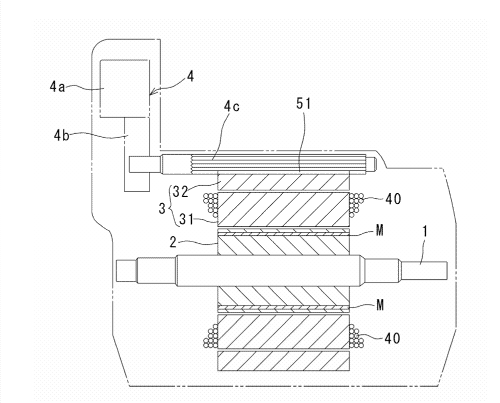
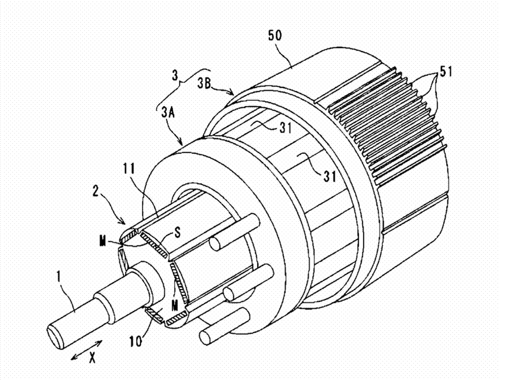
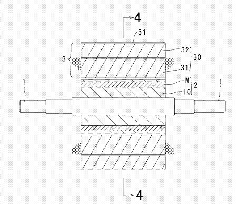
[0099] figure 1 to 6 schematically show a radial gap type motor used as a motor for an electric motorcycle according to a first embodiment of the present invention. As shown in these figures, this radial gap type motor includes a cylindrical rotor 2 having a cylindrical rotor 2 arranged at intervals in the circumferential direction on the outer peripheral portion in an embedded manner, a cylindrical stator 3 and a rotating mechanism 4 . A plurality of permanent magnets M and configured to rotate around the rotation axis 1, the cylindrical stator 3 faces the outer peripheral portion of the rotor 2 in the radial direction through a gap, and the rotation mechanism 4 is configured to make the components that constitute the stator 3 described later The movable split teeth move relatively. Such as figure 2 As shown, the rotor 2 comprises a cylindrical rotor body 10 having an axis of rotation 1 at its axial center. In the outer peripheral portion of the rotor main body 10 , a plu...

no. 2 example

[0155] A rotating electrical machine according to a second embodiment of the present invention is a radial gap type motor used as a motor for an electric motorcycle. The basic structure of this radial gap motor of this second embodiment is the same as that of the motor of the first embodiment except for the structure in which permanent magnets are mounted at the peripheral portion of the rotor 2 . Therefore, the following description will focus mainly on the differences.

[0156] in such as Figure 7 In the illustrated embodiment, each permanent magnet M corresponding to the permanent magnet M in the first embodiment is divided into two divided permanent magnets M1 and M1 arranged at intervals in the circumferential direction of the rotor 2 . On the radially outer side of these divided permanent magnets M1 and M1 , there is provided a holder 15 whose outer peripheral surface is formed in an arc shape. The holder 15 is integrally connected to the rotation center side of the r...


PUM


Abstract

The invention provides an electric rotating machine. A tooth portion 30 of a stator is divided into first and second tooth portions 31, 32 and in a relatively movable manner between a first position in which a magnetic resistance between the tooth portions is small and a second position in which the magnetic resistance is relatively larger than in the first position. When the second tooth portion is in the first position, the following equation is satisfied: (total magnetic resistance of main magnetic circuit C1)<(total magnetic resistance of magnetic short-circuit C2)<=(total magnetic resistance of magnetic circuit between permanent magnets C3). When the second tooth portion is in the second position, it is satisfied: (total magnetic resistance of the magnetic short-circuit C2)<(total magnetic resistance of the main magnetic circuit C1), and (total magnetic resistance of the magnetic short-circuit C2)<=(total magnetic resistance of the magnetic circuit between permanent magnetics C3).

Description

technical field [0001] The present invention relates to a rotating electrical machine preferably used as an electric motor as a drive source of various electric vehicles including, for example, electric motorcycles, and various electric machines. Background technique [0002] Generally, as an electric motor used as a driving source for various electric vehicles including electric motorcycles or for various electric products, a rotor having permanent magnets and configured to rotate around a rotation axis and a motor having stator windings via the rotor Rotating electrical machines are known in which the radial gap faces the stator of the rotor. [0003] In recent years, small and high-performance electric motors are desired as drive sources for use in various electric vehicles including electric motorcycles. In such an electric motor, if the operating range from a high-torque low-revolution range to a low-torque high-revolution range is wide, vehicle running can be obtained...

Claims


Application Information

Patent Timeline
Patent Type & Authority Applications(China)
IPC IPC(8): H02K21/16H02K21/02H02K1/14
CPCH02K21/028
Inventor 清水司日野阳至
Owner YAMAHA MOTOR CO LTD
Why Eureka
Try Eureka