A pulse excitation circuit of a DC and low frequency magnetic signal testing device

A test device, pulse excitation technology, applied in the direction of the magnitude/direction of the magnetic field, magnetic field measurement using the principle of magnetic flux control, electrical components, etc., can solve the problem that the excitation power consumption is difficult to further reduce

Active Publication Date: 2016-08-24
曹宜
View PDF4 Cites 0 Cited by
  • Summary
  • Abstract
  • Description
  • Claims
  • Application Information

AI Technical Summary

Problems solved by technology

The above excitation circuits all use a triode half-bridge as the circuit driver stage, and only one triode is in the conducting state during the circuit operation stage. The common defect is that in the half-bridge, the triode is in the conducting state during part of the time period. The current flows, and this defect causes problems for the two excitation circuits of parallel capacitance and series capacitance respectively: in the case of parallel capacitance excitation circuit, a larger inductance needs to be added, and in the case of series capacitance excitation circuit, the excitation power consumption is difficult Further decrease

Method used


Image

  • A pulse excitation circuit of a DC and low frequency magnetic signal testing device
  • A pulse excitation circuit of a DC and low frequency magnetic signal testing device
  • A pulse excitation circuit of a DC and low frequency magnetic signal testing device

Examples


Embodiment 1

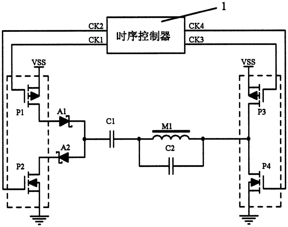
[0055] Parallel capacitive excitation circuit scheme with unidirectional components: such as figure 1 , the CK1 terminal of the timing controller is connected to the gate of the transistor P1 in the first half-bridge unit, the CK2 terminal of the timing controller is connected to the gate of the transistor P2 in the first half-bridge unit, and the CK3 terminal of the timing controller is connected to the second The gate of the transistor P3 in the half-bridge unit, the CK4 terminal of the timing controller is connected to the gate of the transistor P4 in the second half-bridge unit, and the drains of the transistor P1 and the transistor P2 are respectively connected to the first unidirectional element A1 and the second The unidirectional element A2, the joint point of the first unidirectional element A1 and the second unidirectional element A2 is connected to the capacitor C1, the capacitor C1 is connected to the magnetic probe excitation coil M1, and the magnetic probe excitat...

Embodiment 2

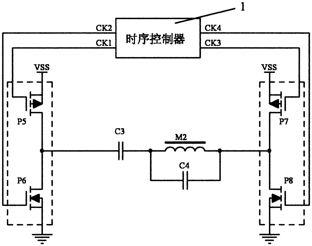
[0067] Parallel capacitive excitation circuit solution without unidirectional elements: In Embodiment 1, the first unidirectional element A1 and the second unidirectional element A2 are removed to obtain this embodiment. like figure 2 , the CK1 terminal of the timing controller is connected to the gate of the transistor P5 in the first half-bridge unit, the CK2 terminal of the timing controller is connected to the gate of the transistor P6 in the first half-bridge unit, and the CK3 terminal of the timing controller is connected to the second The gate of the transistor P7 in the half-bridge unit, the CK4 terminal of the timing controller is connected to the gate of the transistor P8 in the second half-bridge unit, the joint point of the drains of the transistor P5 and the transistor P6 is connected to the capacitor C3, and the capacitor C3 is connected to the magnetic probe The excitation coil M2, the magnetic probe excitation coil M2 is connected to the drain junction of the ...

Embodiment 3

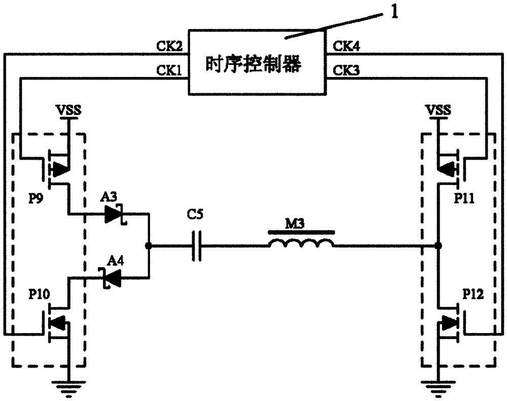
[0076] This embodiment is obtained by removing the capacitor C2 in Embodiment 1. like image 3 , series capacitor excitation circuit: the CK1 terminal of the timing controller 1 is connected to the gate of the transistor P9 in the first half-bridge unit, and the CK2 terminal of the timing controller 1 is connected to the gate of the transistor P10 in the first half-bridge unit, timing control The CK3 terminal of the controller 1 is connected to the gate of the transistor P11 in the second half-bridge unit, the CK4 terminal of the timing controller 1 is connected to the gate of the transistor P12 in the second half-bridge unit, and the drains of the transistor P9 and the transistor P10 are respectively connected to The third unidirectional element A3 and the fourth unidirectional element A4, the joint point of the third unidirectional element A3 and the fourth unidirectional element A4 is connected to the capacitor C5, the capacitor C5 is connected to the magnetic probe excitat...


PUM


Abstract

The invention relates to an impulse excitation technology device of a direct-current low-frequency magnetic signal testing device and control operation steps, in particular to an impulse excitation circuit of the direct-current low-frequency magnetic signal testing device and a control method thereof. The impulse excitation circuit comprises a time sequence controller, two one-way elements, a resonance circuit formed by a capacitor and a probe and a one-way current circuit. The impulse excitation circuit of the direct-current low-frequency magnetic signal testing device has the advantages that a utilized inductor serially connected with a blocking capacitor and used in a conventional circuit is removed, interference from an inductor element with a magnetic core to the probe is avoided, the parallelly connected capacitor resonance circuit is enabled to be applicable to a portable device which is compactly mounted, and meanwhile, power consumption of a serially connected resonance circuit is lowered.

Description

technical field [0001] The invention relates to a pulse excitation circuit, in particular to a pulse excitation circuit of a DC and low frequency magnetic signal testing device. Background technique [0002] The DC and low-frequency magnetic field measurement device composed of the fluxgate principle is widely used in the fields of space and object magnetic field measurement, mine prospecting, shaft measurement, three-dimensional coordinate tracking in virtual reality, etc. At the same time, it is used for DC current and DC leakage current measurement, and in magnetically saturated amplifiers. [0003] The main function of the fluxgate excitation circuit is to output positive and negative symmetrical periodic currents, so that the probe core alternately enters and exits the deep magnetic saturation state, thereby obtaining a high-sensitivity and high-precision induction coil output signal, which is obtained through detection and A voltage signal proportional to the external...

Claims


Application Information

Patent Timeline
Patent Type & Authority Patents(China)
IPC IPC(8): H03B5/08G01R33/04
Inventor 曹宜
Owner 曹宜
Why Eureka
Try Eureka