Synchronous commutation consequent converter with reverse current suppresser

A synchronous rectification and converter technology, which is applied to the output power conversion device, the conversion of DC power input to DC power output, and the conversion of AC power input to DC power output, etc., can solve problems such as voltage surges and eliminate reverse Current, avoid the effect of voltage surge

Active Publication Date: 2013-11-06
DELTA ELECTRONICS INC
View PDF0 Cites 0 Cited by
  • Summary
  • Abstract
  • Description
  • Claims
  • Application Information

AI Technical Summary

Problems solved by technology

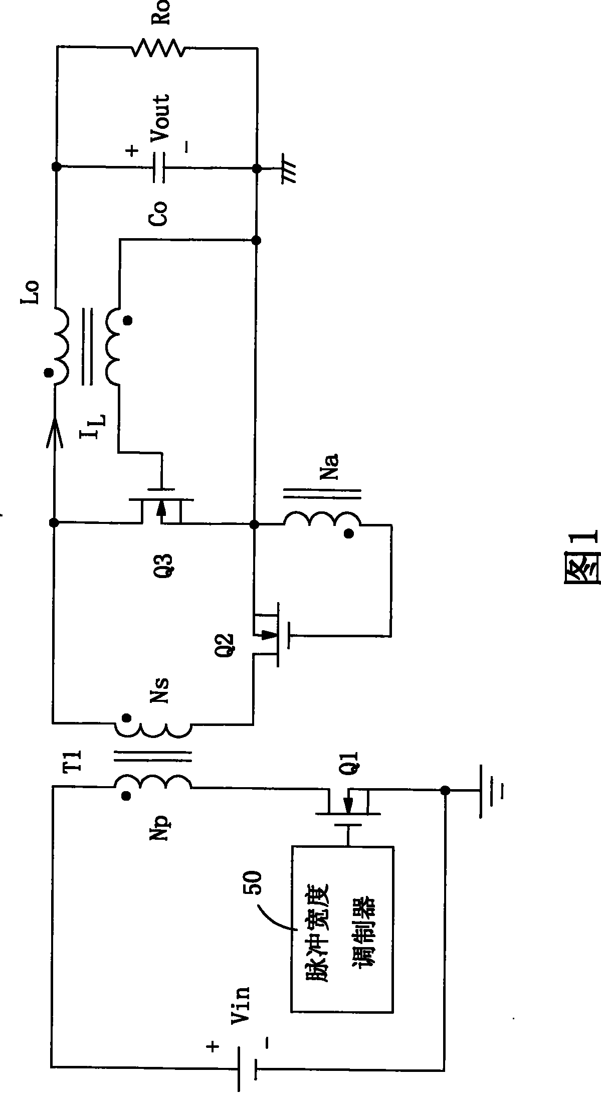
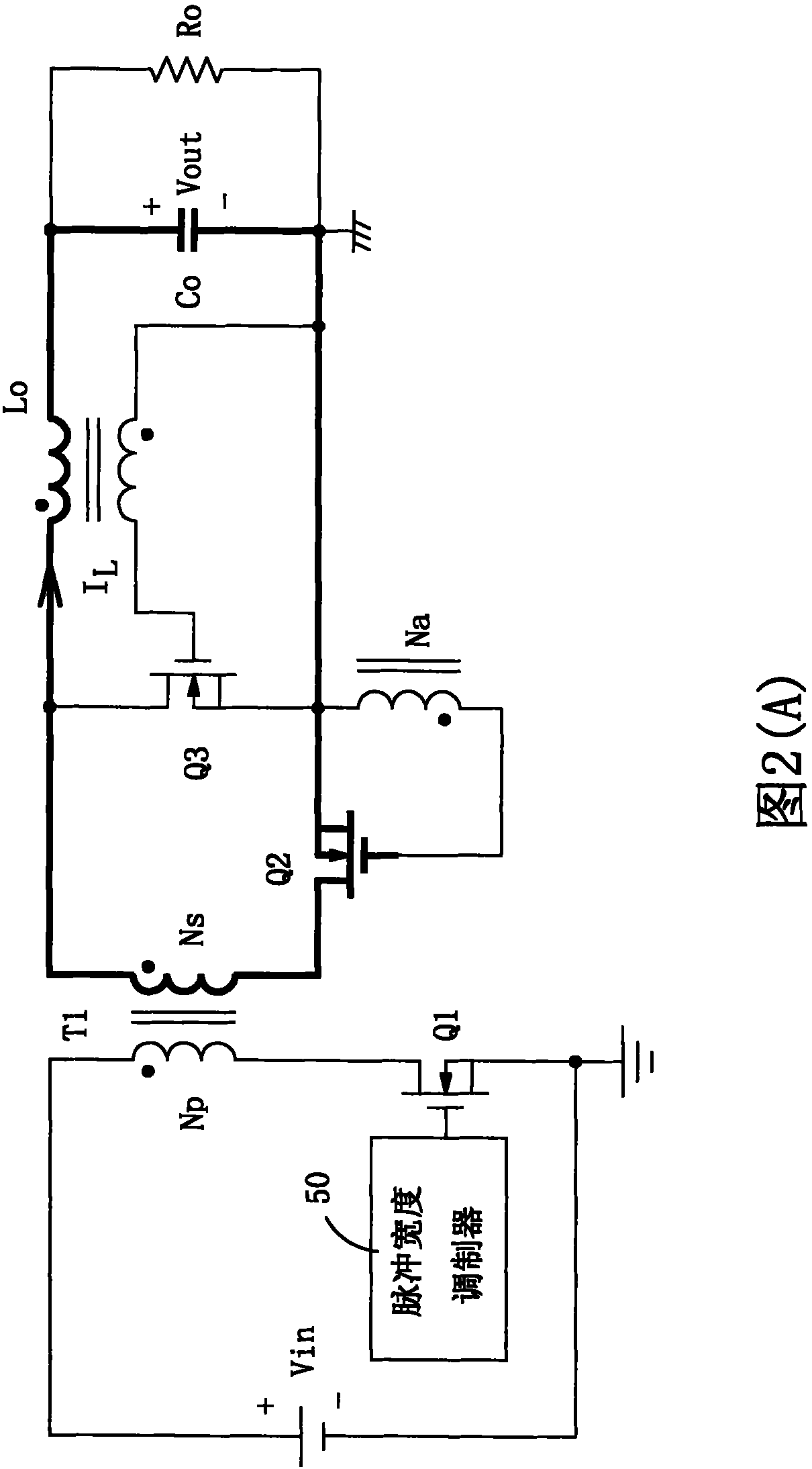
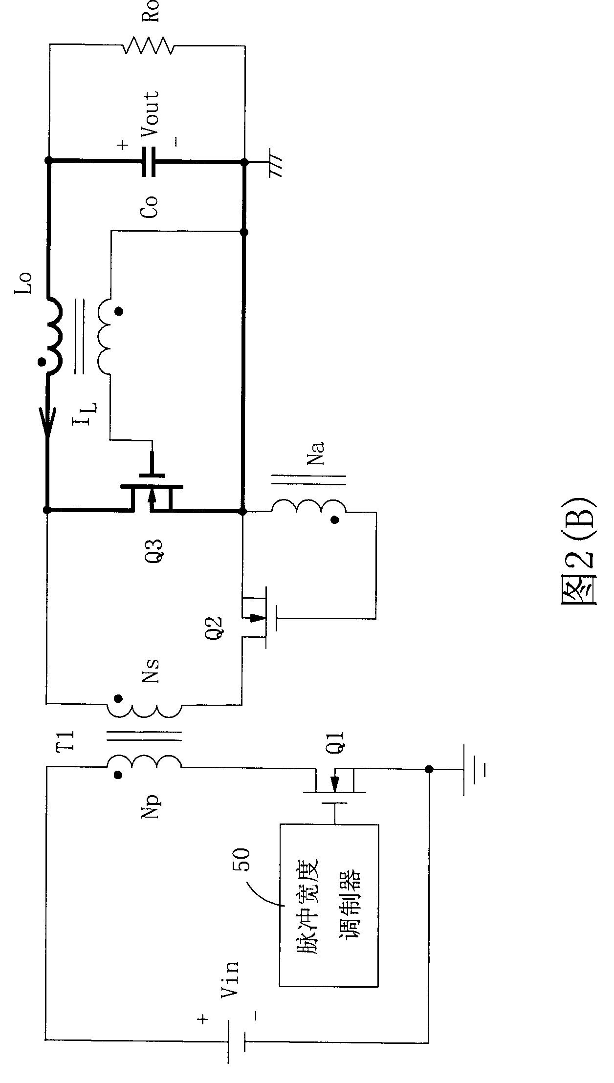
Therefore, a voltage spike is generated between the drain and source of forward switch Q2 and flywheel switch Q3

Method used


Image

  • Synchronous commutation consequent converter with reverse current suppresser
  • Synchronous commutation consequent converter with reverse current suppresser
  • Synchronous commutation consequent converter with reverse current suppresser

Examples


no. 1 example

[0130] Figure 5 shows the waveform diagram of the internal voltage and control input signal of the synchronous rectification forward converter according to the first embodiment of the present invention, and Figure 6 A circuit configuration diagram of the synchronous rectification forward converter and its reverse current suppressor according to the first embodiment of the present invention is shown. In this embodiment, the reverse current suppressor 60 receives a control input signal to determine whether the forward converter is shut down. The phase of the trailing edge of the control input signal will lead the phase of the trailing edge of the output voltage (representing the time point when the input power is interrupted). Such as Figure 6 As shown, the control input signal is designated as an enable signal, which is issued by a control circuit (not shown) of the power supply system where the synchronous rectification forward converter is located, and is used to start t...

no. 2 example

[0136] A second embodiment of the invention is shown in Figure 7 and Figure 8 . Figure 7 A waveform diagram showing the voltage and control signal of the synchronous rectification forward converter and its reverse current suppressor of the second embodiment of the present invention, and Figure 8 A circuit configuration diagram of a synchronous rectification forward converter and its reverse current suppressor according to the second embodiment of the present invention is shown. In this embodiment, the reverse current suppressor 60 is set to generate a voltage detection signal representing the input voltage across the secondary side of the transformer to determine whether a reverse current occurs. exist Figure 8 Among them, the input bulk capacitor (input bulk capacitor) Cb is connected across the primary side of the transformer, which is set to provide a boosted input DC voltage Vin to the forward converter so as to convert the boosted input DC voltage Vin into a regul...


PUM


Abstract

The invention relates to a synchronization rectification straightforward converter with reverse current suppresser which is connected with a grid of a flywheel switch. And the reverse current suppresser is created receiving the control input signal caused by the control circuit of the power supply system at the synchronization rectification straightforwardness converter such as energy signal to detect shut down of the straightforward converter and close the flywheel switch when the input power supply is interrupted according to the shut down of the straightforward converter. Or reverse current suppresser can be designed to detect the attenuation of the input voltage from the two ends of the input bulk capacitor positioned at the primary side of a transformer of the straightforward converter, and to shut off the flywheel switch when the voltage of the two ends of the transformer primary side is fell down less than the output voltage of the straightforward converter. The utility model controls the flywheel switch to shut off quickly through a simple circuit structure and a control mechanism when the input power of the straightforward converter is broke off or before the reverse current is produced, thereby eliminating the reverse current and avoiding harm from the break-down voltage.

Description

technical field [0001] The present invention relates to a synchronous rectification forward converter, more particularly the present invention relates to a synchronous rectification forward converter with a reverse current suppressor, wherein the reverse current suppressor is set to When the input power is interrupted due to shutdown of the forward converter, the flywheel switch of the synchronous rectifier is timely turned off to eliminate the reverse current generated in the synchronous rectifier. Background technique [0002] In a typical forward converter, a main switch is disposed on the primary side of the transformer and connected in series with the primary side winding of the transformer, and a rectifying circuit composed of rectifying diodes is disposed on the secondary side of the transformer. The magnetizing inductance of the primary side winding of the transformer stores energy therein by receiving the current from the voltage input terminal, and transfers the st...

Claims


Application Information

Patent Timeline
Patent Type & Authority Patents(China)
IPC IPC(8): H02M3/24H02M7/527
Inventor 王冠盛刘添华
Owner DELTA ELECTRONICS INC
Why Eureka
Try Eureka