Circuit used for drive control of flow current tube of direct current/direct current converter

A technology of DC converter and drive control, which is applied in the direction of converting DC power input to DC power output, control/regulation systems, instruments, etc. It can solve problems such as freewheeling tube and load damage, and achieve the elimination of reverse current and reverse current. The effect of directing current and stress and improving stability

Active Publication Date: 2012-06-06
ASTEC POWER SUPPLY (SHENZHEN) CO LTD
View PDF5 Cites 0 Cited by
  • Summary
  • Abstract
  • Description
  • Claims
  • Application Information

AI Technical Summary

Problems solved by technology

When the rated value is exceeded, it will damage the freewheel tube and load

Method used


Image

  • Circuit used for drive control of flow current tube of direct current/direct current converter
  • Circuit used for drive control of flow current tube of direct current/direct current converter
  • Circuit used for drive control of flow current tube of direct current/direct current converter

Examples


Embodiment 1

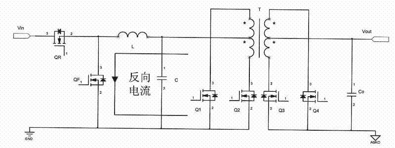
[0044] Such as Figure 7 As shown, a circuit for driving and controlling the freewheeling tube of the DC / DC converter.

[0045] Wherein, the charging and discharging network includes a first resistor R1 and a first capacitor C1, the reference voltage obtaining unit includes a second resistor R2 and a third resistor R3, the comparator includes an operational amplifier U and a fourth resistor R4, and the output control unit includes a field effect transistor Qc and the fifth resistor R5. The finishing tube pulse width modulation signal HD is connected to the first terminal of the first resistor R1, the second terminal of the first resistor R1 is connected to the first terminal of the first capacitor C1, and the inverting terminal of the operational amplifier U, respectively, and the second terminal of the first capacitor C1 is grounded , the first end of the second resistor R2 is connected to the first power supply, the second end is connected to the first end of the third resi...

Embodiment 2

[0064] Such as Figure 17 As shown, a circuit for driving and controlling the freewheeling tube of the DC / DC converter. The difference between this embodiment and the first embodiment lies in: the output control unit part and the comparator part.

[0065]In this embodiment, the charging and discharging network includes a first resistor R1 and a first capacitor C1, the reference voltage obtaining unit includes a second resistor R2 and a third resistor R3, the comparator includes an operational amplifier U and a fourth resistor R4, and the output control unit includes Field effect transistor Qc and fifth resistor R5. The pulse width modulation signal of the sorting tube is connected to the first terminal of the first resistor R1, the second terminal of the first resistor R1 is connected to the first terminal of the first capacitor C1, and the non-inverting terminal of the operational amplifier U, respectively, the second terminal of the first capacitor C1 is grounded, and the s...

Embodiment 3

[0068] Such as Figure 18 As shown, a circuit for driving and controlling the freewheeling tube of the DC / DC converter. The difference between this embodiment and the first embodiment lies in: the reference voltage obtaining unit part.

[0069] In this embodiment, the charging and discharging network includes a first resistor R1 and a first capacitor C1, the reference voltage obtaining unit includes a second resistor R2 and a voltage regulator tube Z, and the output control unit includes a field effect transistor Qc and a fifth resistor R5; the first Resistor R1 is connected to the pulse width modulation signal of the rectifier tube, the second terminal is connected to the first terminal of the first capacitor C1 and the inverting terminal of the operational amplifier respectively, the second terminal of the first capacitor C1 is grounded, and the first terminal of the second resistor R2 is connected to the first terminal of the second resistor R2. A power supply, the second ...


PUM


Abstract

The invention discloses a circuit used for the drive control of a flow current tube of a direct current / direct current converter, which comprises a charge and discharge network, a reference voltage acquisition unit, a comparator and an output control unit; after being processed by the charge and discharge network, a rectifying tube pulse-width modulating signal of the direct current / direct current converter is coupled to a first input of the comparator; reference voltage is led out from the reference voltage acquisition unit and then coupled to a second input of the comparator; the output of the comparator is coupled to a first input of the output control unit; the flow current tube pulse-width modulating signal of the direct current / direct current converter is coupled to a second input of the output control unit; the output of the comparator and the flow current tube pulse-width modulating signal are processed by the output control unit and then outputted to the control end of the flow current tube; the flow current tube pulse-width modulating signal is the pulse signal with duty ratio continuously being increased when the direct current / direct current converter is in a starting transient state and with the duty ratio being constant when the direct current / direct current converter enters in a stable state; and the duty ratio of the flow current tube pulse-width modulating signal and the duty ratio of the rectifying tube pulse-width modulating signal mutually complement.

Description

technical field [0001] The invention relates to a circuit for driving and controlling a freewheeling tube of a DC / DC converter. Background technique [0002] In recent decades, with the continuous development of high-frequency and high-efficiency power converters, the synchronous rectification technology using Metal-Oxide-Semiconductor Field-Effect Transistor (MOSFET) as the switching device has gradually Instead of the traditional diode rectification technology, it has been more and more widely used in power converters. [0003] However, since the MOSFET is a bidirectional switching device, it also brings some new problems when it is used as a freewheeling tube. Such as figure 1 As shown, take the step-down push-pull (BUCK+PUSH-PULL) converter as an example. When switching on and off, the freewheeling tube QF is turned on, and the output capacitor, inductance and freewheeling tube QF form a loop. Such as figure 2 As shown, on the one hand, the output waveform of the c...

Claims


Application Information

Patent Timeline
Patent Type & Authority Patents(China)
IPC IPC(8): H02M1/06H02M3/00
Inventor 程杰斌
Owner ASTEC POWER SUPPLY (SHENZHEN) CO LTD
Why Eureka
Try Eureka