LED driving circuit capable of realizing complete-period sampling of inductive current

A technology of LED drive and inductor current, which is applied in the direction of lamp circuit layout, electric light source, lighting device, etc., can solve the problems of low output current accuracy, increased chip cost, and poor constant current characteristics, so as to improve the output constant current accuracy and simplify the Design, the effect of reducing the volume

Active Publication Date: 2013-06-26
SHANGHAI BRIGHT POWER SEMICONDUCTOR CO LTD
View PDF4 Cites 16 Cited by
  • Summary
  • Abstract
  • Description
  • Claims
  • Application Information

AI Technical Summary

Problems solved by technology

[0004] First, the inductor current sampling circuit can only sample the current flowing through the inductor when the power switch tube is turned on, but cannot detect the current flowing through the inductor when the power switch tube is turned off, and cannot actually sample the output current, only through the internal algorithm of the chip To achieve, the output current accuracy is low, the constant current characteristics are poor, and the compensation circuit is required inside the chip, which increases the cost of the chip
[0005] Second, the auxiliary winding increases system cost and volume

Method used


Image

  • LED driving circuit capable of realizing complete-period sampling of inductive current
  • LED driving circuit capable of realizing complete-period sampling of inductive current
  • LED driving circuit capable of realizing complete-period sampling of inductive current

Examples


Embodiment Construction

[0017] Specific embodiments of the present invention will be described in detail below in conjunction with the accompanying drawings.

[0018] The purpose of the present invention is to provide an LED drive circuit for full-period sampling of the inductor current, so that the output current has high precision, good constant current characteristics, and improves the overall performance of the power supply. At the same time, the power supply circuit does not need an auxiliary winding, which can simplify the design of the LED driving power supply, reduce the volume of the LED driving power supply, and reduce the cost of the LED driving power supply.

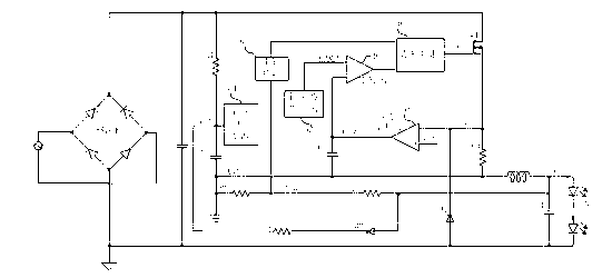
[0019] In order to solve the above-mentioned technical problems, the embodiments of the present invention provide an LED driving circuit for full-period sampling of inductor current. Such as figure 2 As shown, the LED drive circuit includes: a current sampling resistor R4, which is used to sample the current of the inductor L1 and...


PUM


Abstract

The invention discloses an LED driving circuit capable of realizing complete-period sampling of inductive current. The LED driving circuit is used for realizing LED constant-current driving and comprises a rectifier bridge connected with input alternating-current voltage, and an LED load, and the LED load after being connected with an inductor (L1), a power switch (M1) and a sampling resistor (R4) is parallelly connected with a filter capacitor (C1). The LED driving circuit is characterized in that the LED driving circuit switches off the power switch (M1) through a loop control circuit according to current signals flowing through the inductor (L1) when the power switch (M1) is switched on and off and switches on the power switch (M1) according to demagnetizing time of the inductor (L1).

Description

technical field [0001] The invention relates to the technical field of switch-type LED drive power supply, in particular to an LED drive circuit for full-period sampling of inductance current. Background technique [0002] figure 1 is a simplified schematic diagram of a traditional buck LED driver circuit. Such as figure 1 As shown, the alternating current is rectified by the rectifier bridge and then filtered by the capacitor C1 to generate power supply. The resistor R1 and the capacitor C2 generate a low-voltage DC voltage to start the control chip. The transformer has two windings, including a main winding connected between the power supply and the output capacitor of the output LED, and an auxiliary winding connected between the diode D2 and the circuit ground. When the circuit is started, the sampling resistor R2 samples the current information of the main winding to control the output current, the auxiliary winding supplies power to the control chip, and at the same...

Claims


Application Information

Patent Timeline
Patent Type & Authority Applications(China)
IPC IPC(8): H05B37/02
Inventor 孙顺根于得水杨彪
Owner SHANGHAI BRIGHT POWER SEMICONDUCTOR CO LTD
Why Eureka
Try Eureka