

Fluorescence sensor
A fluorescent sensor and fluorescent technology, applied in the field of fluorescent sensors, can solve the problems that the fluorescent sensor 110 is not easy to obtain high detection sensitivity
- Summary
- Abstract
- Description
- Claims
- Application Information
AI Technical Summary
Problems solved by technology
Method used
Image

Examples
no. 1 Embodiment approach >
[0037] Hereinafter, the fluorescence sensor 10 according to the first embodiment of the present invention will be described.
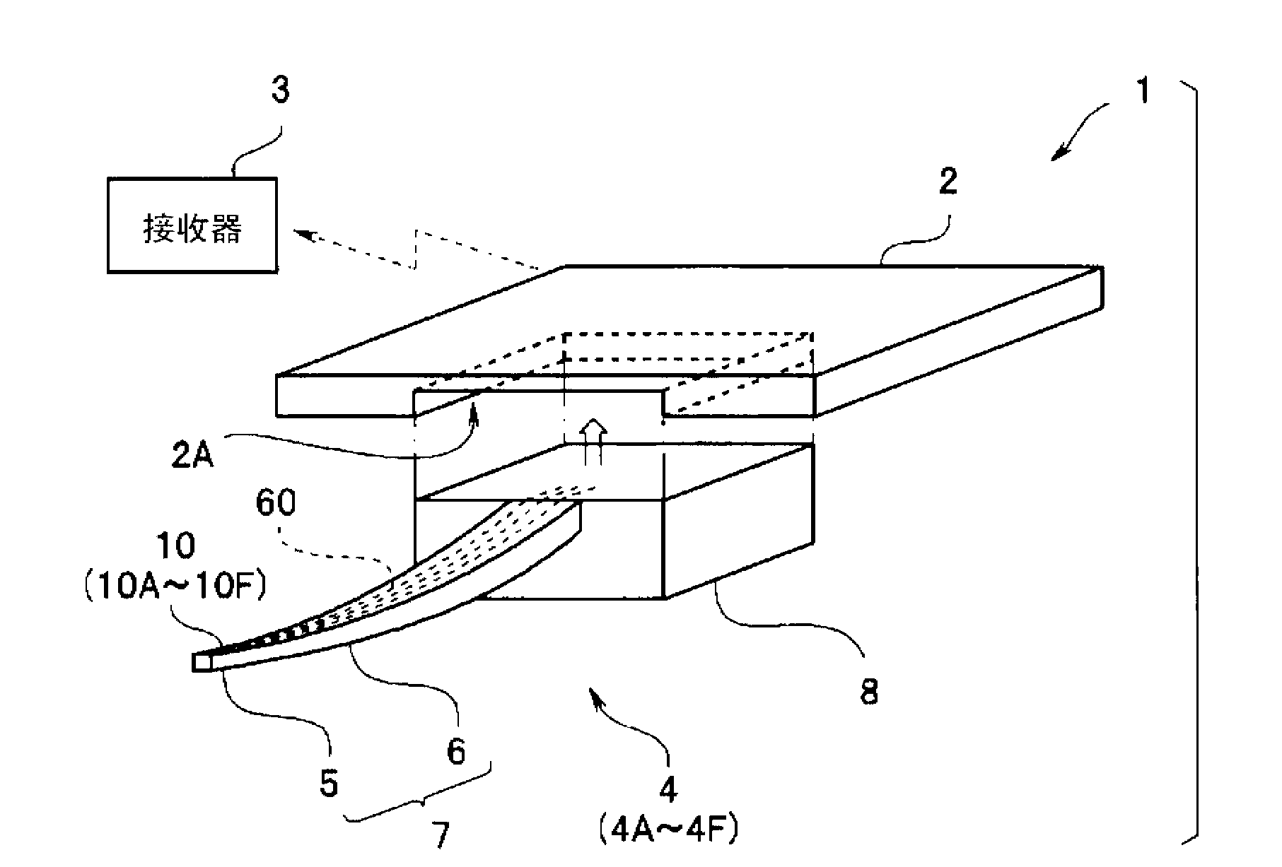
[0038] Such as image 3 As shown, a needle-type fluorescent sensor 4 having a fluorescent sensor 10 constitutes a sensor system 1 together with a main body 2 and a receiver 3 .
[0039] That is, the sensor system 1 has a needle-type fluorescent sensor 4 , a main body 2 , and a receiver 3 that receives and stores a signal from the main body 2 . The signal transmission and reception between the main body part 2 and the receiver 3 is performed wirelessly or by wire.
[0040] The needle-type fluorescence sensor 4 is provided with: a needle part 7 having a needle front end part 5 and an elongated needle main body part 6, and the front end part 5 includes a fluorescence sensor 10 as a main functional part; of the connector part 8. The needle tip portion 5, the needle body portion 6, and the connector portion 8 may also be integrally formed of the same mat...
no. 2 Embodiment approach >
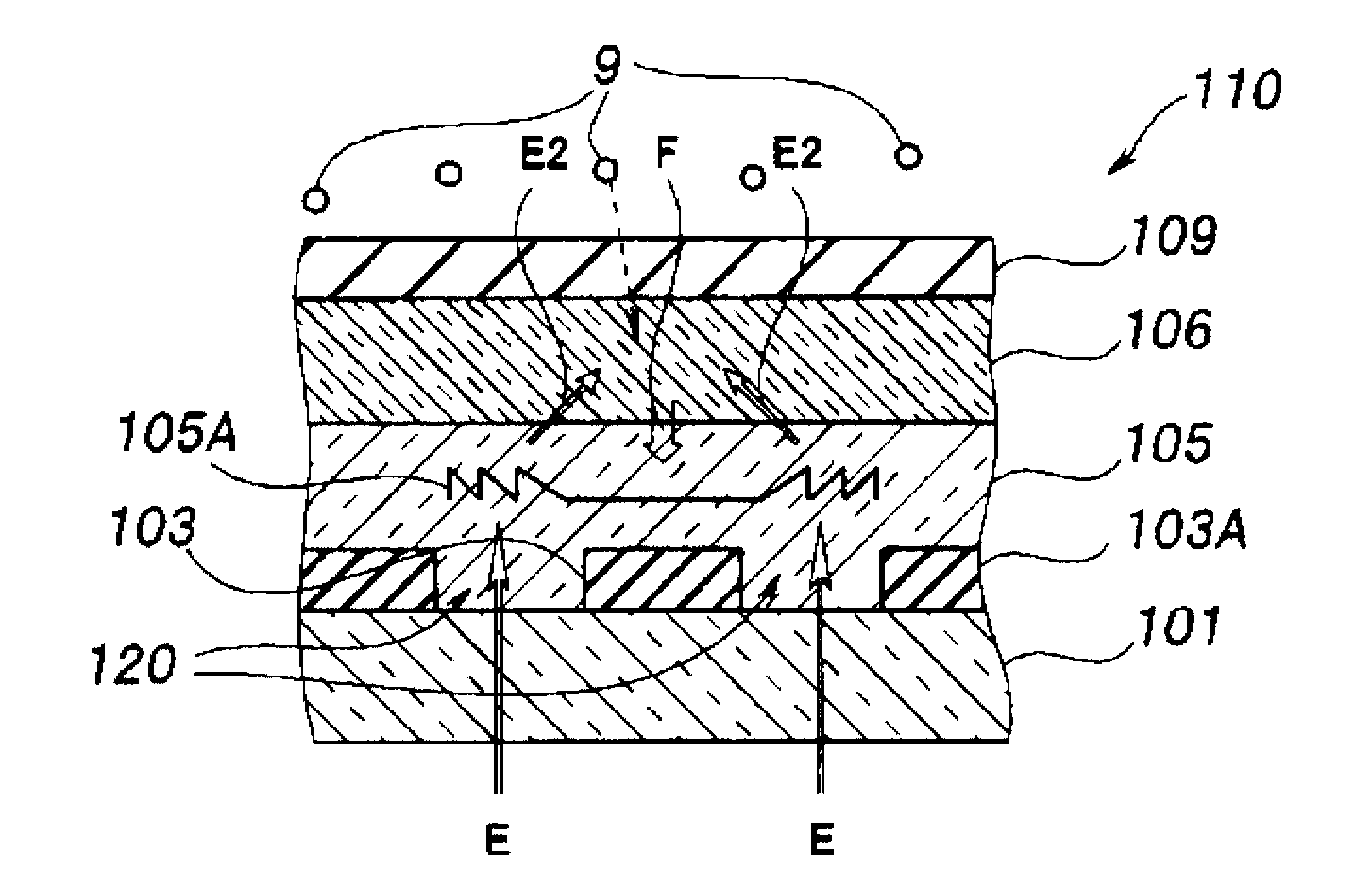
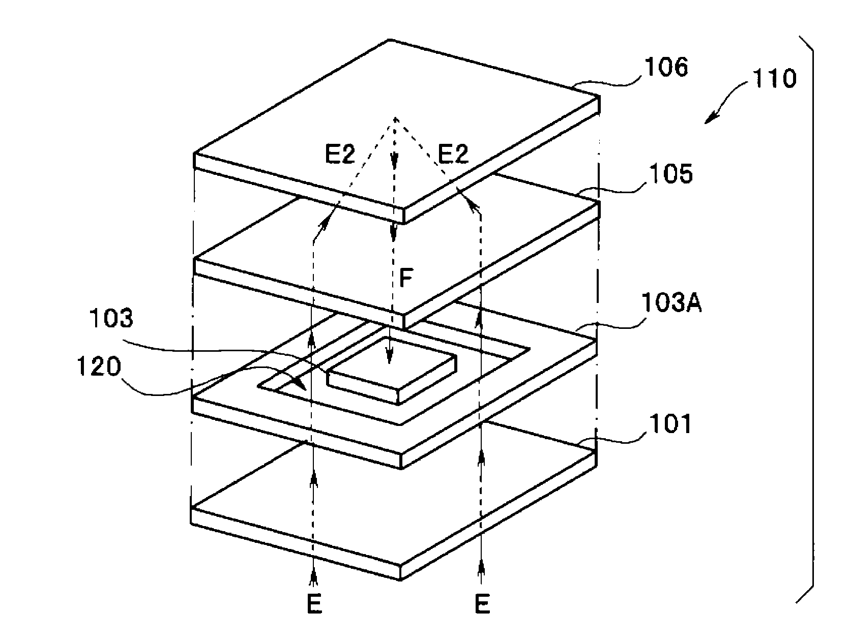
[0097] Next, a needle-type fluorescence sensor 4B including the fluorescence sensor 10B according to the second embodiment of the present invention will be described. Since the fluorescence sensor 10B of the present embodiment is similar to the fluorescence sensor 10 of the first embodiment, the same components are given the same reference numerals and their descriptions are omitted.
[0098] Such as Figure 8 As shown, in addition to the PD element 13A as the first photoelectric conversion element formed on the side surface 24 of the concave portion 23 of the detection substrate portion 20B (the wall surface 45 of the through hole 46 of the frame-shaped substrate 40 ), the fluorescence sensor 10B also has The bottom surface 22 (upper surface of the wiring substrate 30B) is formed with the PD element 13B as the second photoelectric conversion element.
[0099] A silicon oxide layer 42B serving as a third protective layer for protecting the PD element 13B and an optical filter...
no. 3 Embodiment approach >
[0117] Next, a needle-type fluorescence sensor 4D including a fluorescence sensor 10D according to a modified example of the third embodiment of the present invention will be described. The fluorescence sensor 10D of this modified example is similar to the fluorescence sensor 10 etc. of 1st Embodiment, Therefore The same code|symbol is attached|subjected to the same component, and description is abbreviate|omitted.
[0118] The detection substrate portion 20D of the fluorescence sensor 10D is integrally produced by a silicon wafer 20DW which is a semiconductor substrate. That is, the concave portion 23D of the detection substrate portion 20D is a concave portion formed on the first main surface 21 of the silicon wafer 20DW by, for example, an etching method.
[0119] Next, use Figure 10A ~ Figure 10E , the method of manufacturing the fluorescence sensor 10D will be described. In addition, in Figure 10A ~ Figure 10E 10D is a partial cross-sectional view of the region of on...
PUM
 Abstract
Description
Claims
Application Information