Lifter bore drilling cutter assembly and lifter bore machining method

A drilling tool and tappet hole technology, which is applied in drilling tool accessories, drilling/drilling equipment, metal processing equipment, etc., can solve the problems of high engine oil consumption, inconsistent roughness, long processing cycle, etc., and achieve improvement Tool durability, ensuring roughness requirements, and solving the effect of uneven force on the tool

Active Publication Date: 2013-07-03
GUANGXI YUCHAI MASCH CO LTD
View PDF5 Cites 6 Cited by
  • Summary
  • Abstract
  • Description
  • Claims
  • Application Information

AI Technical Summary

Problems solved by technology

When processing the tappet hole 11, when the drill bit 13 passes through the main oil passage hole 12, because there is no support force on one side of the drill bit, the force on the drill bit 13 will be uneven, and floating drilling will occur, making the exit and entrance of the bottom hole X, Y The diameter of the two directions is out of tolerance, which leads to the inability to correct the ellipse of the bottom hole in the post-reaming process, and finally the diameter and roughness of the tappet hole 11 cannot meet the process requirements
[0003] In the current process of processing tappet holes 11, the drilling tappet hole bottom hole (determining whether the tappet hole can be reamed), reaming tappet hole and reaming tappet hole, although in the same equipment, the same process is completed, but because the cylinder Due to the limitation of the body structure, when processing tappet hole 11, the tool can only be fed from the bottom of the cylinder body. The maximum outer diameter of the tool holder is allowed to be φ35mm, the minimum length is 440mm, and the length-to-diameter ratio of the tool is greater than 12. This kind of ordinary high-speed steel tool holder and The clamping structure with the tool makes it difficult to control the jump of the tool tip during the machining process, and the hole is prone to ellipse during drilling and reaming (the changes in the X and Y directions of the exit and entrance are all greater than 0.03mm) and the roughness is inconsistent.
When it is out of tolerance, it will have an impact on the performance of the diesel engine, which will cause problems such as high fuel consumption and loud noise of the engine.
In addition, the processing cycle is relatively long, and the tool cost is relatively high

Method used


Image

  • Lifter bore drilling cutter assembly and lifter bore machining method
  • Lifter bore drilling cutter assembly and lifter bore machining method
  • Lifter bore drilling cutter assembly and lifter bore machining method

Examples


Embodiment Construction

[0027] A specific embodiment of the present invention will be described in detail below in conjunction with the accompanying drawings, but it should be understood that the protection scope of the present invention is not limited by the specific embodiment.

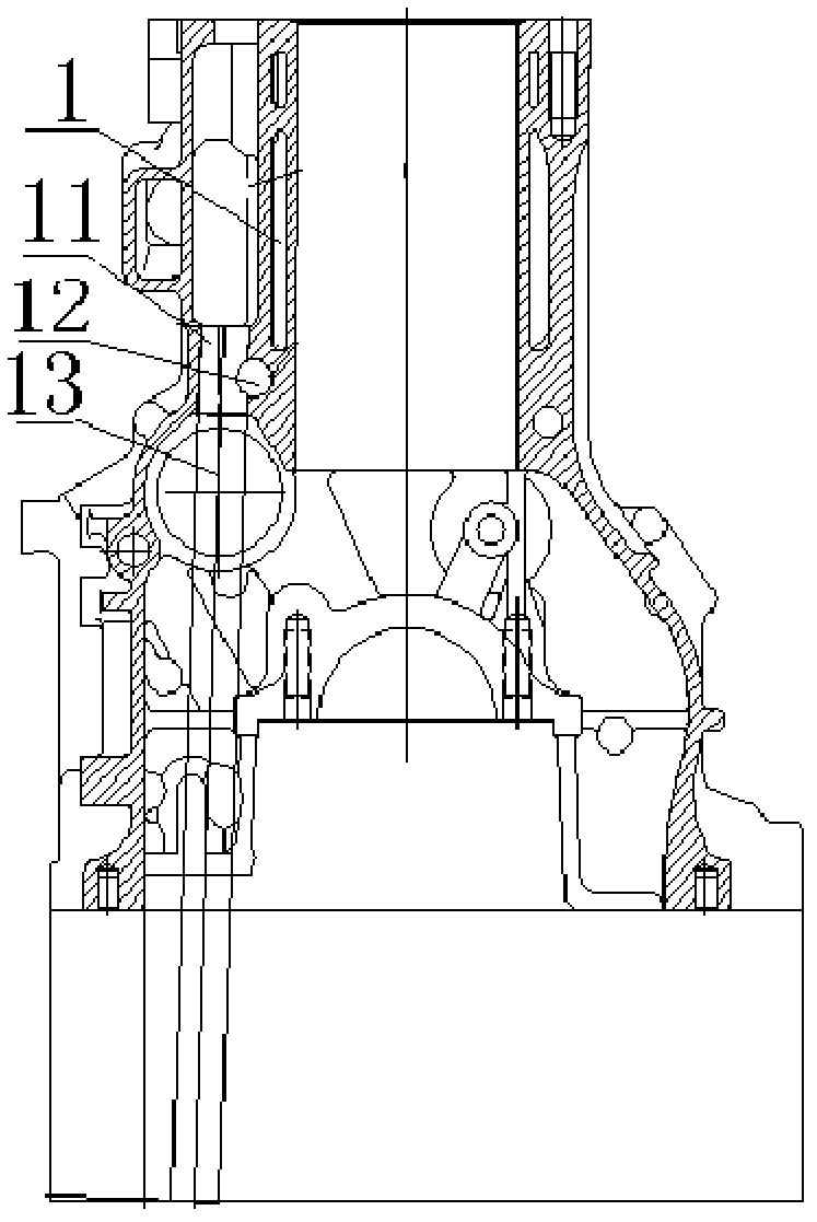
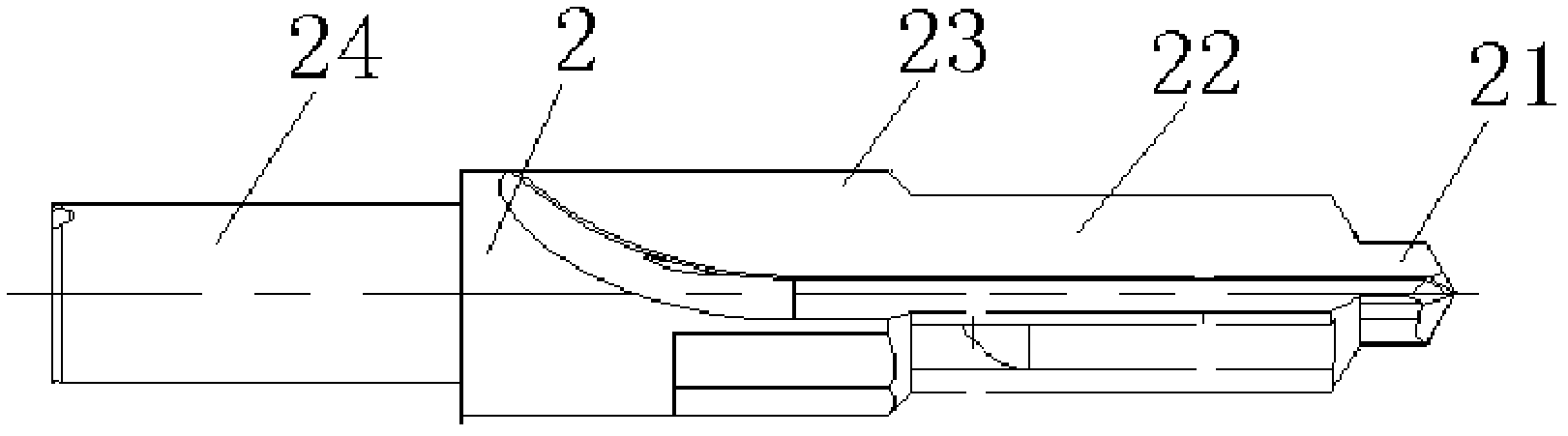
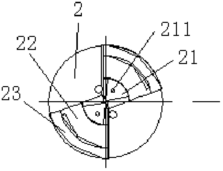
[0028] see figure 1 , the tappet hole drilling tool assembly includes: inner cooling centering step drill bit 2 and heavy metal shrink fit tool holder 3. Among them, such as figure 2 with image 3 As shown, the inner cooling centering step drill bit 2 is used to drill and expand the bottom hole of the tappet hole; the inner cooling centering step drill bit 2 has a stepped structure with inner cooling holes, specifically including: drill core 21, reaming section 22, chamfering section 23 And the drill shank 24, the drill core 21 is located at the rightmost end of the internal cooling and centering stepped drill bit 2, and has the smallest diameter, so that when the drill core 21 drills the bottom hole of the tappet hole ...


PUM


Abstract

The invention discloses a lifter bore drilling cutter assembly and a lifter bore machining method. The cutter assembly comprises an internal-cooled pilot step drill bit and a heavy-metal hot shrink-fit shank. The internal-cooled pilot step drill bit is of a step structure with internal cooling holes and specifically comprises a core bit, an expanding section, a chamfering section and a drill bit shank, wherein the diameter of the core bit is the smallest to enable the core bit to avoid cross main oil passage holes when the core bit drills the bottom hole of the lifter bore; the internal cooling holes are formed in the end part of the core bit; the expanding section is close to the core bit; the chamfering section is connected with the expanding section; and the internal-cooled pilot step drill bit is installed on the heavy-metal hot shrink-fit shank through the drill bit shank. By machining the bottom hole of the lifter bore through the heavy-metal hot shrink-fit shank in cooperation with internal-cooled pilot step drill bit, the problems that the cutter is unevenly stressed and the elliptical aperture is apt to occur during the machining of offset cross lifter bores are well solved. In addition, by using a diamond honing reamer to hone and ream the lifter hole, the requirement on the roughness of the lifter hole is satisfied and the durability of the cutter is improved.

Description

technical field [0001] The invention relates to the field of engines, in particular to a tappet hole drilling tool assembly and a processing method for the tappet hole. Background technique [0002] At present, the tappet hole structure of a certain type of cylinder block 1 is that the tappet hole 11 and the main oil passage hole 12 intersect (see for details figure 1 ). When processing the tappet hole 11, when the drill bit 13 passes through the main oil passage hole 12, because there is no support force on one side of the drill bit, the force on the drill bit 13 will be uneven, and floating drilling will occur, making the exit and entrance of the bottom hole X, Y The diameters in the two directions are out of tolerance, which leads to the inability to correct the ellipse of the bottom hole in the post-reaming process, and finally the diameter and roughness of the tappet hole 11 cannot meet the process requirements. [0003] In the current process of processing tappet hol...

Claims


Application Information

Patent Timeline
Patent Type & Authority Applications(China)
IPC IPC(8): B23B51/06B23B51/08B23B35/00
Inventor 潘韦周杨贻计黄翃修
Owner GUANGXI YUCHAI MASCH CO LTD
Why Eureka
Try Eureka