
Component transfer machine

A component and rack technology, applied in the field of component transfer equipment, can solve the problems of high labor intensity and low efficiency, and achieve the effects of saving labor, improving efficiency and improving work efficiency

Active Publication Date: 2015-08-12
BEIJING TORCH CO LTD
View PDF9 Cites 0 Cited by
  • Summary
  • Abstract
  • Description
  • Claims
  • Application Information

AI Technical Summary

Problems solved by technology

High labor intensity and low efficiency

Method used


Image

  • Component transfer machine
  • Component transfer machine
  • Component transfer machine

Examples


Embodiment Construction

[0071] The present invention will be described in further detail below in conjunction with the accompanying drawings and specific embodiments, but not as a limitation of the present invention.

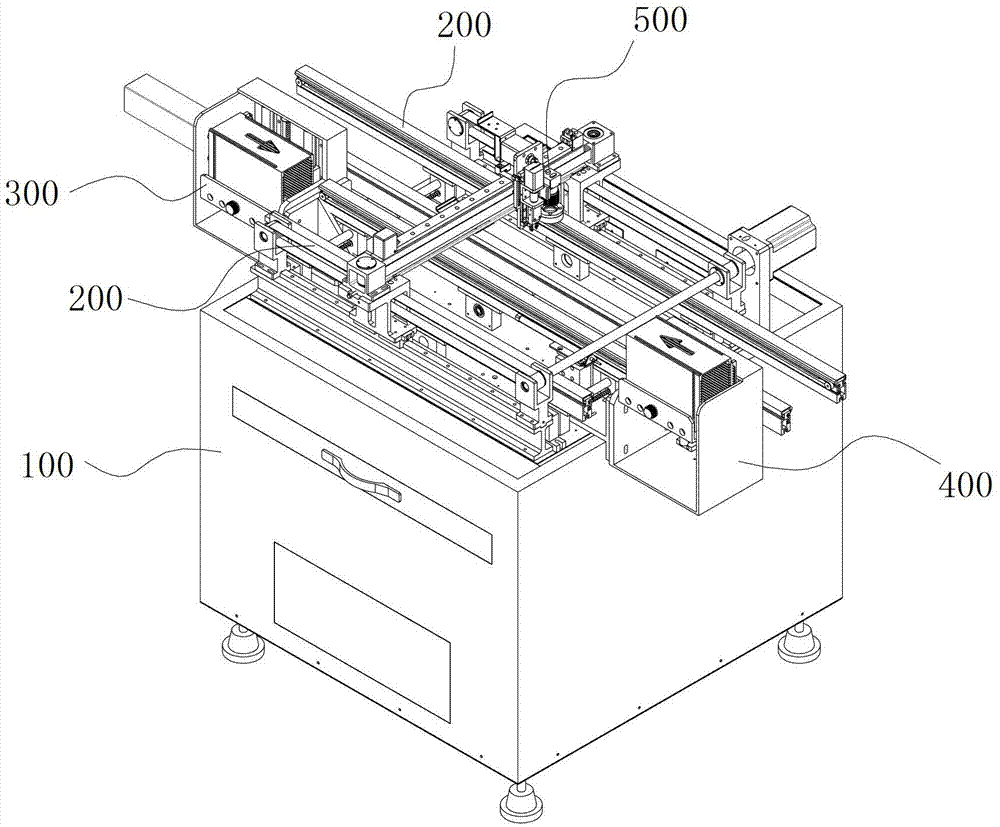
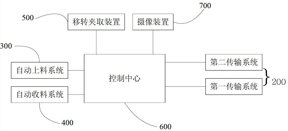
[0072] figure 1 It is a structural schematic diagram of the component transfer machine of the present invention; figure 2 It is a structural block diagram of the component transfer machine of the present invention. like figure 1 As shown, the component transfer machine includes:

[0073] Rack 100;

[0074] Two conveying systems 200 are arranged on the frame 100 and are used to convey the carrier board and the packing box respectively;

[0075] The automatic feeding system 300 is fixedly connected with the frame 100, and is arranged at the feeding end of the conveying system for conveying the carrier plates, and sends the carrier plates to the conveying system in sequence;

[0076] The automatic material receiving system 400 is fixedly connected with the frame 100, and is arranged a...


PUM


Abstract

The invention discloses an element shift machine which comprises a rack, two conveying systems, an automatic charging system, an automatic receiving system, a shift clamping device, and a control center, wherein the two conveying systems are arranged on the rack and used for conveying material carrying plates and packaging boxes respectively; the automatic charging system is fixedly connected with the rack, arranged at a charging end of the conveying system for conveying the material carrying plates, and used for sending the material carrying plates to the conveying system sequentially; the automatic receiving system is fixedly connected with the rack, arranged at a receiving end of the conveying system for conveying the material carrying plates, and used for automatically collecting the material carrying plates after shifting; the shift clamping device is arranged on the rack and moves in a three-dimensional space to shift elements; the control center controls motion of the conveying systems, the automatic receiving system, the automatic charging system and the shift clamping device to shift the elements; and the shift clamping device rotates by a certain angle after clamping an element, and then clamps up the element. The element shift machine can shift the elements in a mechanical mode, saves labor, and is high in efficiency.

Description

technical field [0001] The invention relates to the technical field of component transfer equipment, in particular to a component transfer machine for component boxing or transfer. Background technique [0002] In manufacturers such as component processing and assembly, it is often necessary to transfer components from one carrier to another. For example, a transparent cover plate needs to be set in front of the lens of the camera (or video) equipment to protect the lens. The lens cap produced by the manufacturer needs to be transferred from the loading plate to the packaging box, packed in the box, and then sent to the customer. At present, the transfer of various components is mostly performed manually by staff. Labor intensity is big, and efficiency is low. For this reason, machine operation is required instead of manual operation. [0003] In view of the many problems and defects in the above-mentioned existing component transfer technology, the inventors conducted r...

Claims


Application Information

Patent Timeline
Patent Type & Authority Patents(China)
IPC IPC(8): B65G59/02B65G57/03B65G15/12B65G47/22B65G47/91B65G47/74B65B5/04
Inventor 赵永先张延忠杜伟涛
Owner BEIJING TORCH CO LTD
Learn More