Cooling tower airflow generating set

A technology for power generation devices and cooling towers, which is applied to steam engine devices, machines/engines, mechanical equipment, etc., and can solve the problems of no more than 40% and large heat loss

Inactive Publication Date: 2013-07-03
洛阳希诺能源科技有限公司
View PDF4 Cites 0 Cited by
  • Summary
  • Abstract
  • Description
  • Claims
  • Application Information

AI Technical Summary

Problems solved by technology

However, in modern steam power cycles, even if measures such as ultra-high pressure steam, reheating, and reheating are adopted, the thermal efficiency still does not exceed 40%, and the energy that is taken away by the cooling water through the condenser and discharged into the atmosphere accounts for about 60%. %, the low-temperature heat emitted by the cooling tower to the atmosphere is quite large. Taking a 300MW thermoelectric unit as an example, the heat discharged into the atmosph

Method used


Image

  • Cooling tower airflow generating set

Examples


Embodiment Construction

[0013] For further elaborating the technical means and effects that the present invention takes to reach the intended invention purpose, below in conjunction with accompanying drawing and preferred embodiment, to its specific implementation, structure, feature and its specific implementation mode, structure, feature and Efficacy, detailed as follows.

[0014] The aforementioned and other technical contents, features and effects of the present invention will be clearly presented in the following detailed description of preferred embodiments with reference to the drawings. Through the description of the specific implementation, it should be possible to obtain a deeper and more specific understanding of the technical means and effects of the present invention to achieve the intended purpose, but the attached drawings are only for reference and description, not for the purpose of the present invention. be restricted.

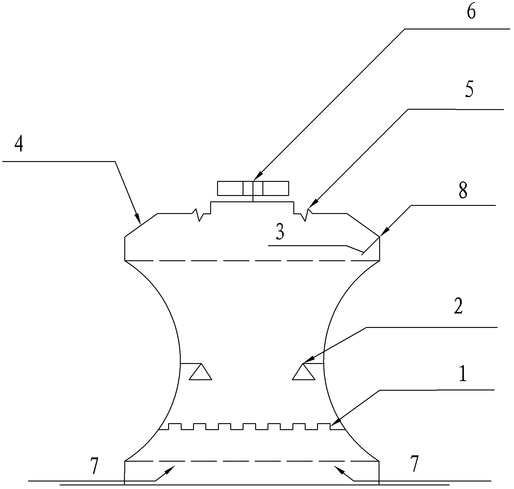
[0015] see figure 1 Shown is a schematic structural view of ...


PUM


Abstract

The invention relates to a cooling tower airflow generating set which comprises a high temperature steam pipeline, a cold water spraying head, a flow board, an inclined cover plate, a flow guiding plate and a hot air generating set, wherein the high temperature steam pipeline is arranged at the lower part of a cooling tower and above an air inlet in the lower part of the cooling tower; the cold water spraying head is arranged in the cooling tower and above the high temperature steam pipeline, and faces the high temperature steam pipeline; the flow board is fixed in channel steel fixed in the top of the cooling tower in a downwards-inclined manner through a fixing device; a circle of flow guiding plate is arranged on the inclined cover plate; and the hot air generating set is arranged in the center of the inclined cover plate. The high temperature steam pipeline is sprayed through the cold water spraying head, the spraying is combined with the air inversed flow to produce a large amount of hot steam, and the hot steam is converted into electric energy, so that the heat energy produced in exhausting steam of the cooling tower is recovered and used at a low cost, and the generating set is recycled and very practical.

Description

technical field [0001] The invention relates to a cooling tower, in particular to a cooling tower hot air flow power generation device. Background technique [0002] In the earliest thermal power plants in my country, the cooling of circulating water was achieved by building many large cooling pools. The cooling pools for cooling circulating water have many defects, such as large area, serious pollution, large heat loss, and large investment. After the 1980s, my country switched to cement tower hyperbolic cooling towers to cool circulating water. Its advantages are small footprint, compact layout, small heat loss and water loss, and good cooling effect. However, in modern steam power cycles, even if measures such as ultra-high pressure steam, reheating, and reheating are adopted, the thermal efficiency still does not exceed 40%, and the energy that is taken away by the cooling water through the condenser and discharged into the atmosphere accounts for about 60%. %, the low...

Claims


Application Information

Patent Timeline
IPC IPC(8): F01K27/02
Inventor 曲长春沈恒涛曲长胜
Owner 洛阳希诺能源科技有限公司
Why Eureka
Try Eureka