Map display method, apparatus for controlling map display and navigation apparatus
A display method and map technology, applied in the field of navigation, to achieve the effect of saving computing resources
- Summary
- Abstract
- Description
- Claims
- Application Information
AI Technical Summary
Problems solved by technology
Method used
Image

Examples
Embodiment Construction
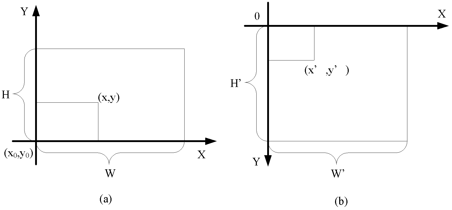
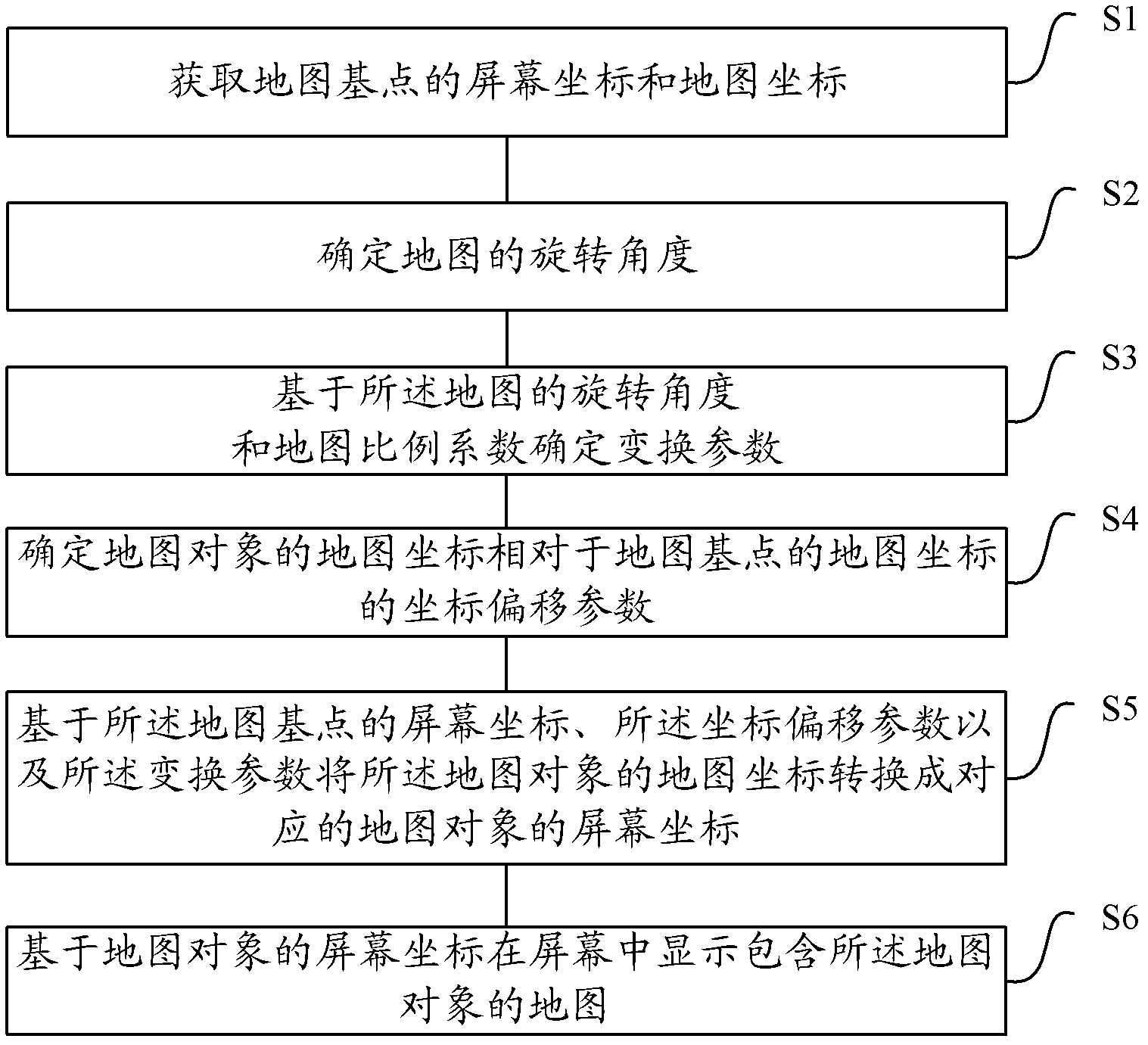
[0029] Aiming at the problems of the prior art, the inventor provides a map display method and a device for controlling the map display after research, which can use any point on the screen as the position of the current parking space, and after changing the position of the current parking space, based on the original parking space The screen coordinates of (map base point), the coordinate offset parameters of the map coordinates of the map object relative to the map coordinates of the map base point, and the transformation parameters determined according to the map rotation angle and the map scale factor convert the map coordinates of the map object into corresponding screen coordinates, allowing for faster redrawing of the navigation map and saving computational resources within the navigation device.
[0030] In order to make the above objects, features and advantages of the present invention more comprehensible, specific implementations of the present invention will be desc...
PUM
 Abstract
Description
Claims
Application Information