Optical proximity correction method

An optical proximity correction, adjacent edge technology, applied in optics, originals for opto-mechanical processing, special data processing applications, etc., can solve the problem of limited optical proximity correction effect, etc. Circulation, the effect of improving efficiency

Inactive Publication Date: 2013-07-03
SEMICON MFG INT (SHANGHAI) CORP
View PDF7 Cites 32 Cited by
  • Summary
  • Abstract
  • Description
  • Claims
  • Application Information

AI Technical Summary

Problems solved by technology

[0006] Existing optical proximity correction methods

Method used


Image

  • Optical proximity correction method
  • Optical proximity correction method
  • Optical proximity correction method

Examples


Example Embodiment

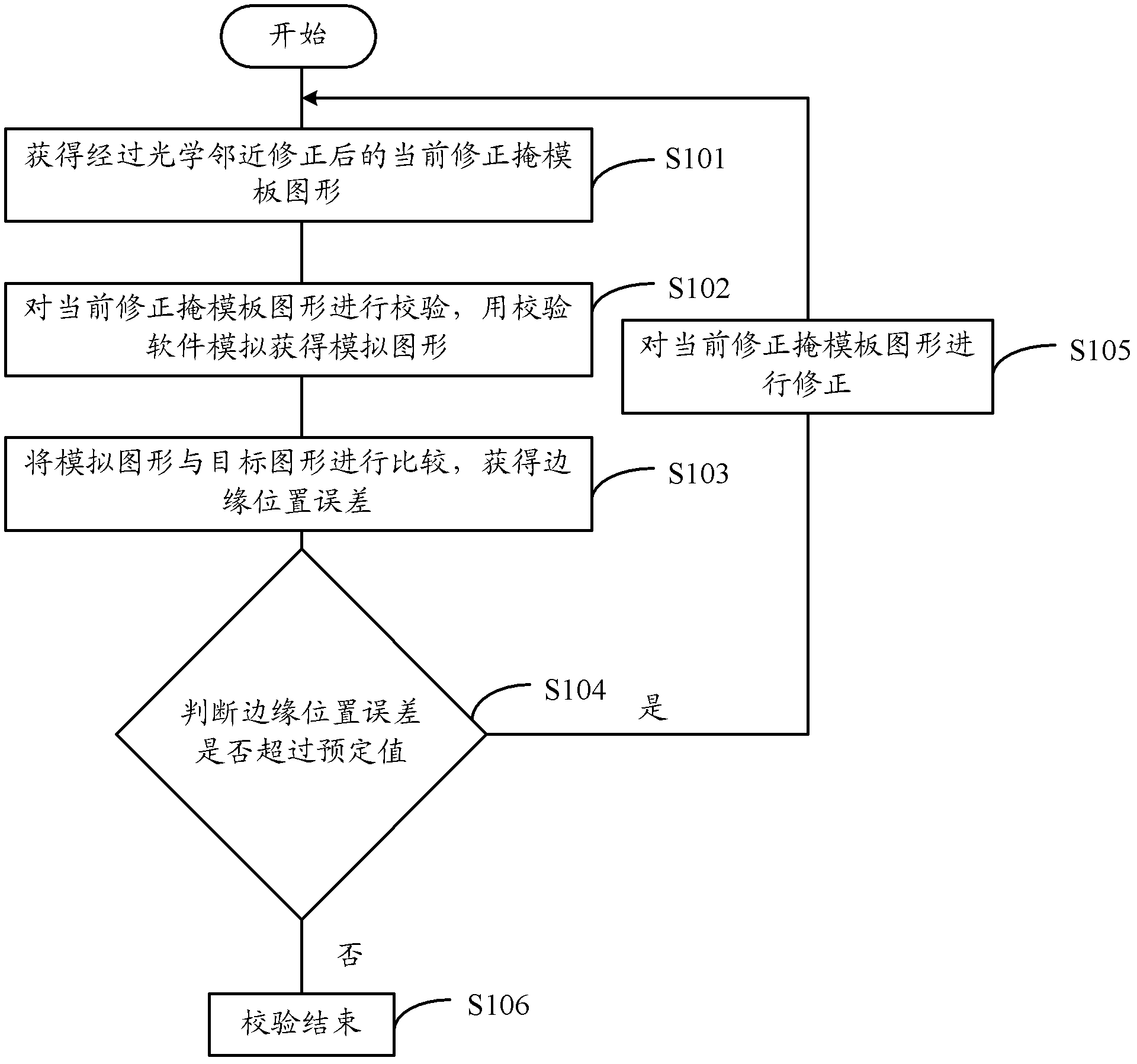
[0028] In the existing optical proximity correction method, the simulated graph is compared with the target graph to obtain the edge placement error (EPE). When the edge placement error (EPE) exceeds a predetermined value, the corresponding correction edge will move outward , Get the corrected mask pattern, then re-simulate the corrected mask pattern to obtain the re-simulated simulation pattern, and then compare the re-simulated simulated pattern with the target pattern to obtain the edge position error and judge whether the edge position error exceeds the predetermined Value, and so on, until the edge position error is within the predetermined value.

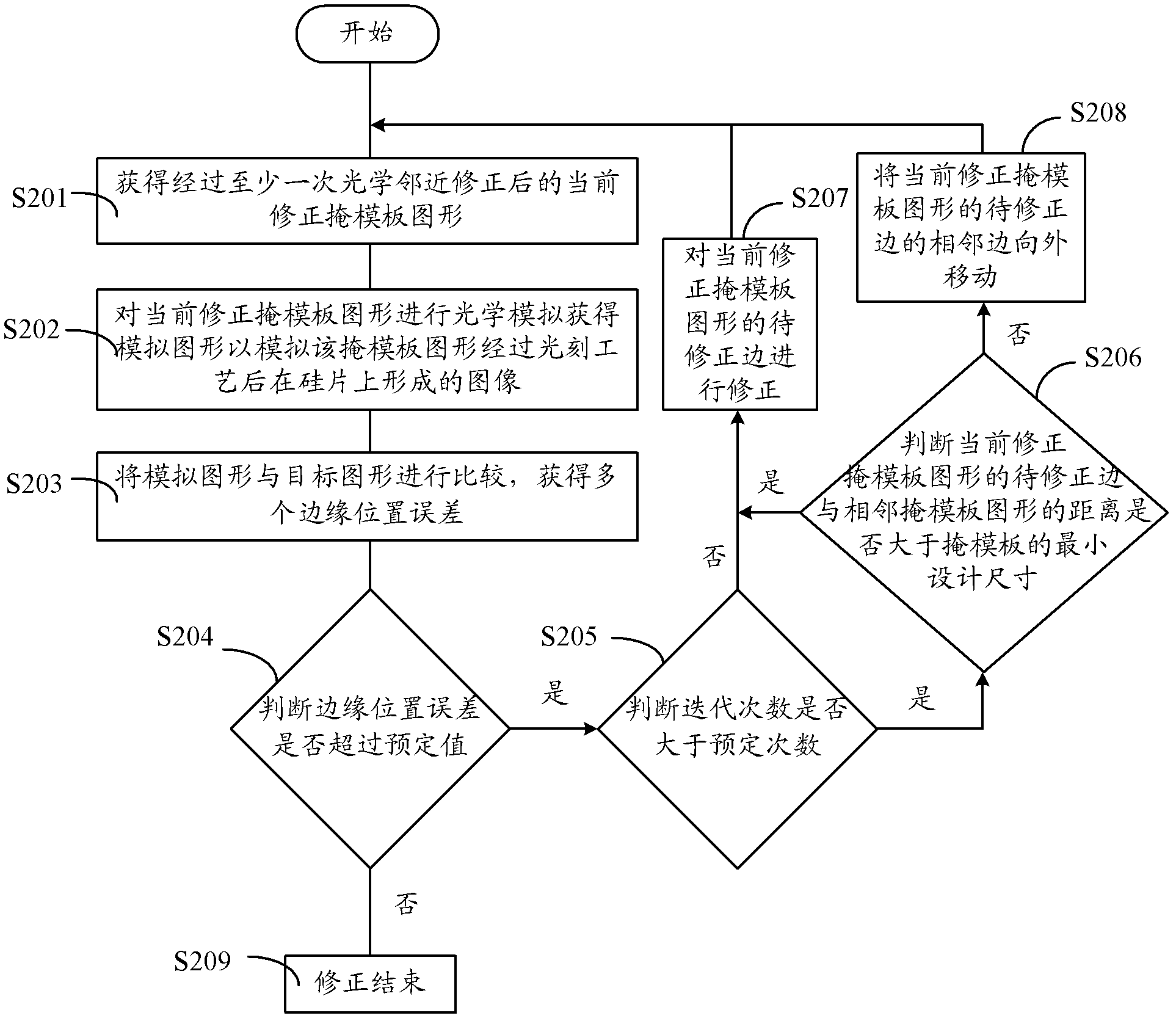
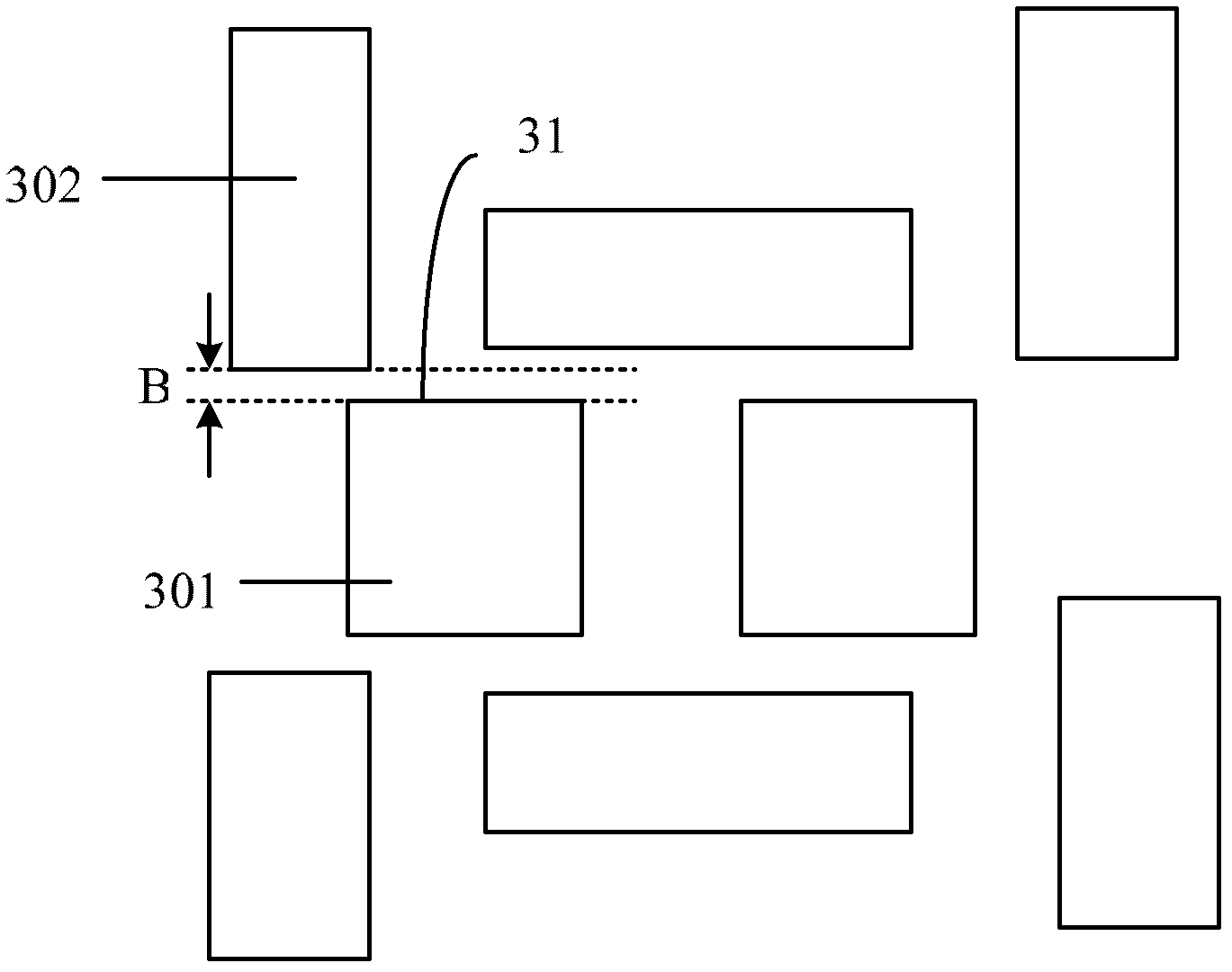
[0029] In order to improve the practical application ability of optical proximity correction, mask rule check (MRC) is also applied to the existing optical proximity correction (OPC) process, that is, between the corrected mask pattern and the adjacent mask pattern The distance must be greater than the minimum design size of the ...


PUM


Abstract

An optical proximity correction method includes the following steps: acquiring a current correction mask plate figure subjected to at least one time of optical proximity correction, and performing optical simulation on the current correction mask plate figure to acquire a simulation figure; comparing the simulation figure and a target figure to obtain an error of multiple border positions; when the error of the border positions is greater than a preset value and the distance from a to-be-corrected edge of the current correction mask plate figure to an adjacent mask plate figure is greater than the minimum design size of a mask plate, correcting the to-be-corrected edge of the current correction mask plate figure; when the error of the border positions is greater than a preset value and the distance from a to-be-corrected edge of the current correction mask plate figure to an adjacent mask plate figure is equal to the minimum design size of the mask plate, moving outwards an adjacent edge of the to-be-corrected edge of the current correction mask plate figure; and repeating the procedures until the error of the border positions is within the preset value. The method disclosed by the embodiment of the invention improves the efficiency of optical proximity correction.

Description

Technical field [0001] The invention relates to the field of semiconductor manufacturing, in particular to an optical proximity correction method. Background technique [0002] In the semiconductor manufacturing process, in order to overcome a series of optical proximity effects (Optical Proximity Effect, OPE) caused by the reduction of critical dimensions (CD), the industry has adopted many resolution enhancement technologies (Resolution Enhancement Technology, RET). ), including optical proximity correction, Phase Shifting Mask (PSM) and Off Axis Illumination (OAI) technologies. [0003] The model-based optical proximity correction (MBOPC) method is one of the optical proximity correction methods, also called the simulated optical proximity correction method. It mainly compares the simulated graphics to be exposed with the target graphics, and establishes the correction mode of the graphics to be exposed. The simulator is then used to perform a series of complex correction calcu...

Claims


Application Information

Patent Timeline
IPC IPC(8): G03F1/36G06F17/50
Inventor 张婉娟
Owner SEMICON MFG INT (SHANGHAI) CORP
Why Eureka
Try Eureka