System for measuring and controlling rotating speed

A speed measurement and control system technology, applied in the direction of electric speed/acceleration control, etc., to achieve the effect of reducing connection gap, convenient control, and light weight

Active Publication Date: 2013-07-03
沈阳飞机设计研究所扬州协同创新研究院有限公司
View PDF6 Cites 7 Cited by
  • Summary
  • Abstract
  • Description
  • Claims
  • Application Information

AI Technical Summary

Problems solved by technology

[0004] The design of the test scheme and the construction of the platform are particularly important. The predecessors proposed to use a stepping motor as the power to drive the turntable to rotate to simulate the rotor effect. The advantage of this method is that it can conveniently control the speed and maintain the stability of the structural dynamic characteristics, so as to test the structural dynamic characteristics. , however, the impact of the connection gap and the additional mass of the motor on the test has become a problem that is difficult to solve

Method used


Image

  • System for measuring and controlling rotating speed
  • System for measuring and controlling rotating speed
  • System for measuring and controlling rotating speed

Examples


Embodiment Construction

[0016] Attached below Figure 1-7 The present invention is described in detail with specific examples.

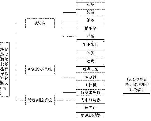
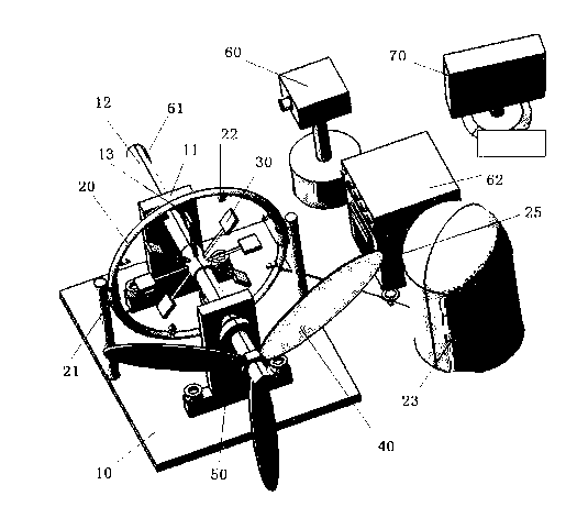
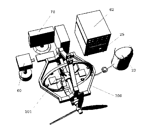
[0017] figure 1 with figure 2 It is the structural composition diagram and schematic diagram of the first embodiment of the rotor effect simulation device of the scaled model of the wing crane engine of the present invention, which is composed of Figure 1~2 It can be seen that the structure of the simulation device is composed of three parts: the test bench, the jet flow control system, and the rotational speed measurement control system; The system includes: nozzle bracket (nozzle ring bracket 20, nozzle side bracket 21), nozzle 22, air source 23, regulating valve 24, controller 25, industrial computer 70; the speed measurement control system includes: photoelectric speedometer 60, photosensitive sheet 61, Data acquisition instrument 62, electromagnetic brake 50, industrial computer 70.

[0018] The test bench is a base 10 with a slideway, the base 10 is provided wit...


PUM


Abstract

The invention provides a system for measuring and controlling a rotating speed. The system mainly comprises a photoelectric speed measuring device 60, a light sensing sheet 61, a data acquisition instrument 62 and an electromagnetic brake 50, wherein the light sensing sheet 61 is arranged at an end part of a rotating shaft 12; the photoelectric speed measuring device 60 and the light sensing sheet 61 are arranged correspondingly; and the electromagnetic brake 50 penetrates the rotating shaft 12, and is arranged on the rotating shaft 12 on the other side opposite to the light sensing sheet 61.

Description

technical field [0001] The invention belongs to the field of aircraft design, and in particular relates to a rotational speed measurement control system of an aircraft engine rotor effect simulation device using a non-contact power source as power. Background technique [0002] The design of modern large passenger aircraft widely adopts the layout form of hanging the engine under the wing. In terms of structural layout, this kind of hanging engine is often far away from the root of the wing and extends out of the leading edge of the wing. Due to the flexibility of the wing and the engine hanger, when the wing When torsional vibration and in-plane bending occur, the rotation axis of the engine rotor will vibrate in pitch and yaw angles. According to gyroscope theory, the angular motion of the axis of the rotating body will cause gyro torque, that is, the rotor effect; this rotor effect is bound to The system composed of the aircraft wing and the engine and even the structural...

Claims


Application Information

Patent Timeline
Patent Type & Authority Applications(China)
IPC IPC(8): G05D13/62
Inventor 张发明邱涛张亮
Owner 沈阳飞机设计研究所扬州协同创新研究院有限公司
Why Eureka
Try Eureka