Built-in permanent magnet motor

A permanent magnet, built-in technology, applied in the direction of magnetic circuit rotating parts, magnetic circuit shape/style/structure, synchronous motor with stationary armature and rotating magnet, etc., can solve unexpected parasitic effects, quadrature Reduce inductance, increase high-order harmonics, etc., to improve the effect of excessive cogging torque and suppress high-order harmonics

Active Publication Date: 2013-07-03
ADLEE POWERTRONIC
View PDF8 Cites 13 Cited by
  • Summary
  • Abstract
  • Description
  • Claims
  • Application Information

AI Technical Summary

Problems solved by technology

[0005] However, the above-mentioned various technical solutions for improving cogging torque will produce undesirable parasitic effects
For example, in the previous patent, because the air gap of the quadrature axis of the motor is increased, the inductance of the quadrature axis is greatly reduced, and the reluctance torque is also reduced accordingly.
When the cogging torque is lower than a certain level, the high-order harmonics of the induced voltage will increase instead, especially when using a strong ...

Method used


Image

  • Built-in permanent magnet motor
  • Built-in permanent magnet motor
  • Built-in permanent magnet motor

Examples


Embodiment Construction

[0032] In order to describe the technical content of the present invention in detail, it will be described in detail below in conjunction with the implementation manners and accompanying drawings.

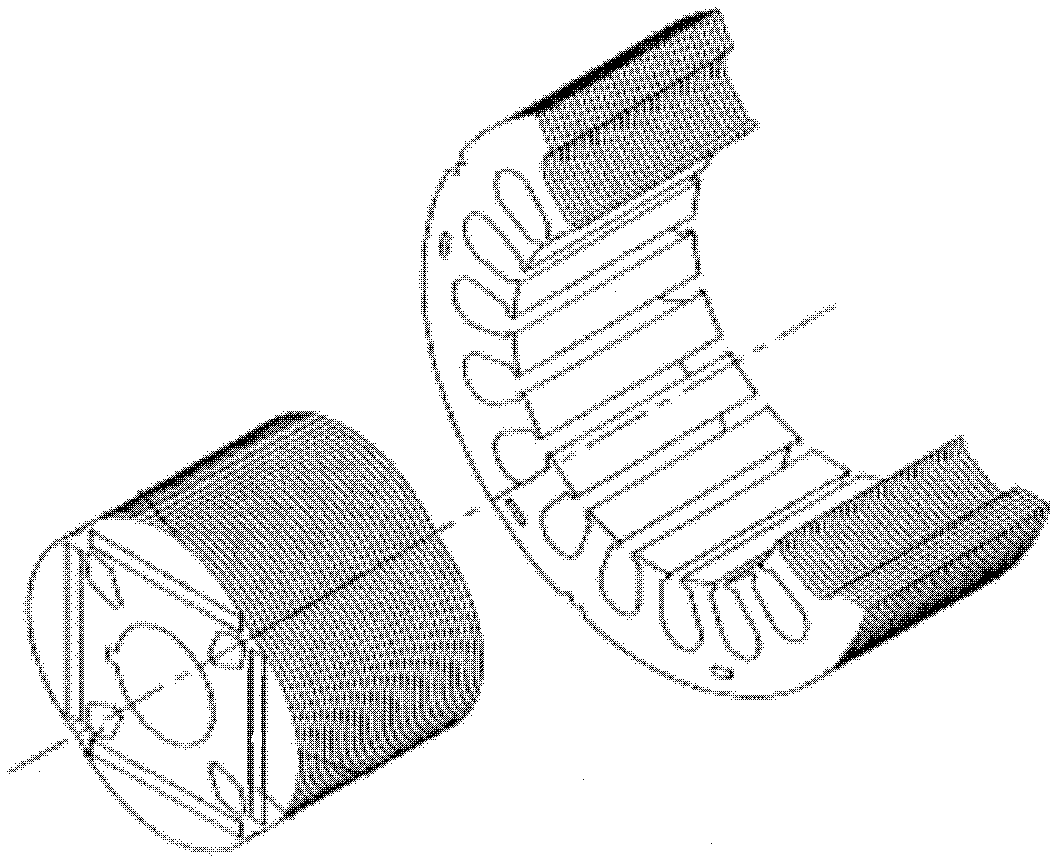
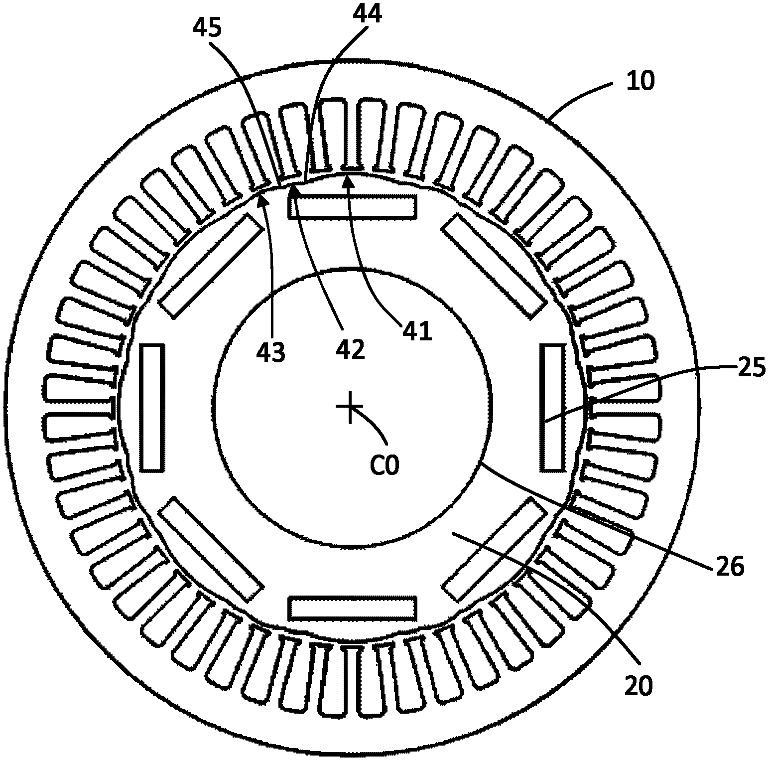
[0033] Such as figure 2 with image 3 As shown, the present invention is described with the end view of the motor stator and rotor, including a stator 10, a rotor 20, a plurality of magnet slots 25 for the built-in permanent magnets, and the center of the rotor 20 for the rotation axis (not shown in the figure) Show) through the shaft hole 26 of the pivot.

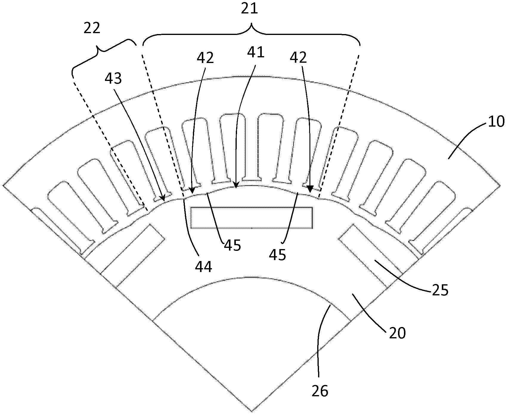
[0034] image 3 yes figure 2 A partial enlargement of the figure to clearly show the shape of the outer edge of the rotor. In the present invention, the outer edge of the rotor of the motor is planned with a plurality of main magnetic pole faces 21 and inter-pole faces 22, and each inter-pole face 22 is between two adjacent main magnetic pole faces 21; the main magnetic pole faces 21 and the interpolar pole surface 22 ar...


PUM


Abstract

The invention discloses a built-in permanent magnet motor. Main polar faces and interpolar faces of a rotor of the motor are formed by connecting a plurality of arcs of eccentric circles not concentric with the circle center of the rotor, so that an air gap is adjusted, and a purpose of reducing a cogging torque of the motor is achieved, and higher harmonic during motor operation is reduced according to regular hierarchic air gap thickness variation. According to the motor, quadrature-axis inductance of the motor is increased in a mode of adopting the air gap thickness of the specific interpolar face and keeping the preset widths of the interpolar faces, so that a reluctance torque of the motor is increased, and torsion of the motor is increased.

Description

technical field [0001] The invention relates to a motor rotor, and refers to a built-in permanent magnet motor rotor capable of increasing reluctance torque, reducing cogging torque and high-order harmonics. Background technique [0002] There is a built-in permanent magnet rotor motor with a uniform air gap. In order to increase its reluctance torque, a technical scheme of reducing the pole surface of the main magnetic pole is adopted. Another significance of this technical scheme is to expand the pole surface between poles. Increase the inductance ratio of the quadrature axis and the direct axis to increase the reluctance torque of the motor. However, the increase in the quadrature axis inductance leads to an increase in the cogging torque, and the cogging torque will lead to the generation of pulsating ripple torque, and the motor will generate vibration and noise, which has a great impact on the efficiency of the motor, especially for vehicle driving, When robot (or mec...

Claims


Application Information

Patent Timeline
IPC IPC(8): H02K21/16H02K1/27
Inventor 朱守昱
Owner ADLEE POWERTRONIC
Why Eureka
Try Eureka