Light emitting diode (LED) light-emitting device directly driven by alternating current

A light-emitting device, alternating current technology, applied in the direction of electric light source, lighting device, electric lamp circuit layout, etc., can solve the problem of not fundamentally solving the problem of AC voltage luminous flicker, damage to LED devices, driving current fluctuation, etc., to facilitate secondary integration The effect of packaging, reducing power loss, and suppressing common mode interference

Active Publication Date: 2013-07-03
SICHUAN SUNFOR LIGHT
View PDF5 Cites 15 Cited by
  • Summary
  • Abstract
  • Description
  • Claims
  • Application Information

AI Technical Summary

Problems solved by technology

This patent does not fundamentally solve the phenomenon of light flickering caused by periodic fluctuations in AC voltage
[0006] It can be seen that there is a shortcoming in the disclosed LED AC driving technology: the driving current of the LED will fluct

Method used


Image

  • Light emitting diode (LED) light-emitting device directly driven by alternating current
  • Light emitting diode (LED) light-emitting device directly driven by alternating current
  • Light emitting diode (LED) light-emitting device directly driven by alternating current

Examples


Embodiment 1

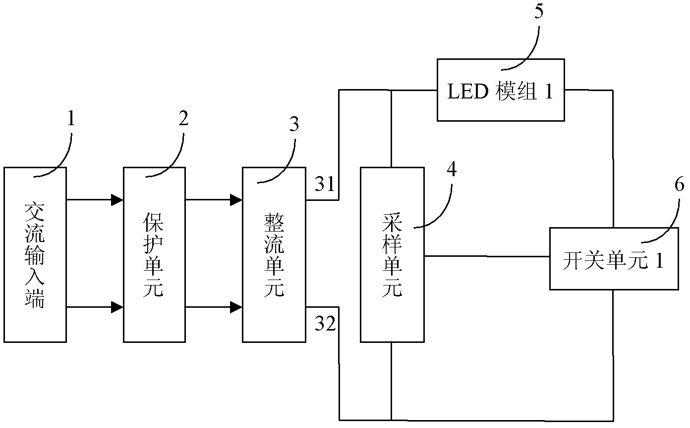
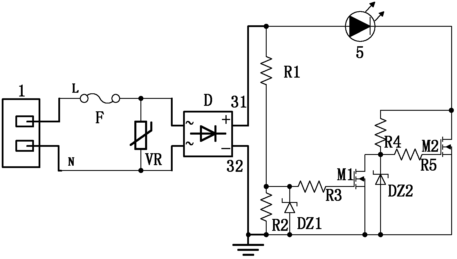
[0042] see figure 1 with figure 2 , the lighting device in this example includes an AC input terminal 1, a protection unit 2, a rectification unit 3, a sampling unit 4, a switch unit 6 and an LED module 5, and the number of LED modules 5 in this example is 1 (ie n=1). The first output terminal of the rectifier unit in this example is a positive DC output terminal 31 , and the positive terminal 31 is connected to the second output terminal DC output negative terminal 32 through the switch unit 6 of the LED module 5 . seefigure 1 . The AC input terminal 1 is connected to the L terminal (phase line) and the N terminal (neutral line) of the AC power, and the AC power is introduced into the protection unit 2 . The protection unit 2 provides the basic protection function for the whole device. It is composed of a varistor VR and a fuse F. The fuse F is connected in series with the phase line, and the varistor is connected in parallel between the phase line and the neutral line. Se...

Embodiment 2

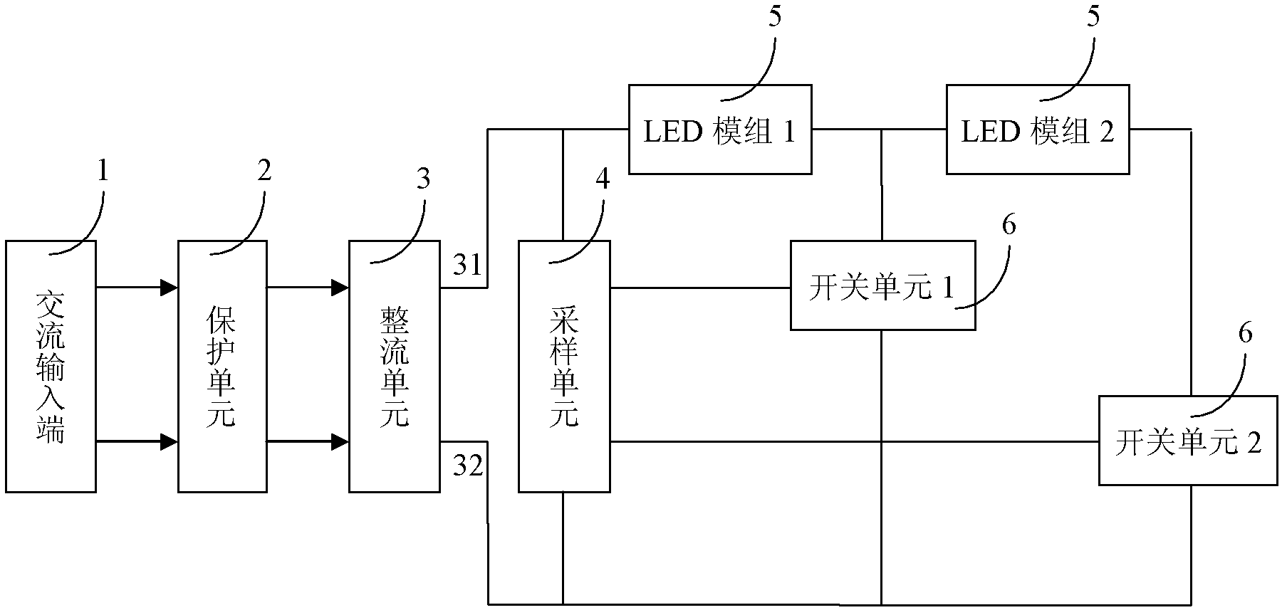
[0047] Such as image 3 As shown, there are 2 LED modules 5 in the light-emitting device of this example, and 2 switch units 6, and the positive terminal 31 of the rectifier unit 3 passes through 2 LED modules and the second switch unit 6 (marked as switch unit 2 in the figure, other The switching unit is labeled similarly) to the negative terminal 32 of the rectifying unit 3, and between the first LED module 5 and the second LED module 5, there is a channel formed by the first switching unit 6 and the negative terminal of the rectifying unit 3 32 connections. In this example, all the switch units 6 are connected to the sampling unit 4 .

Embodiment 3

[0049] Such as Figure 4 As shown, there are three LED modules 5 of the lighting device in this example, and three switch units 6, and the positive terminal 31 of the rectifier unit 3 is connected to the negative terminal 32 of the rectifier unit 3 through three LED modules and the third switch unit 6, Between the first LED module 5 (marked as LED module 1 in the figure, and other LED modules are marked similarly) and the second LED module 5, there is a channel and rectification unit composed of the first switch unit 6 3 negative terminal 32 connection. Between the second LED module 5 and the third LED module 5 , there is a channel formed by a second switch unit 6 connected to the negative terminal 32 of the rectifier unit 3 . In this example, all the switch units 6 are connected to the sampling unit 4 .

[0050] The circuit schematic diagram of the device in this example is shown in Figure 5 As shown, its working principle and specific circuit structure are similar to tho...


PUM


Abstract

The invention relates to an alternating current direct driving technology of a light emitting diode (LED) light-emitting device. Specific to the defects of light emitting flicker caused by directly driving an LED light-emitting device by alternating current in the prior art, the invention discloses an LED light-emitting device directly driven by alternating current. An LED light-emitting device circuit is composed of n levels of LED modules in cascade connection, a sampling unit is used for properly presetting turn-off and switch-on voltages of each level of LED modules corresponding to a switch unit, and therefore flicker phenomenon caused in the process of alternating voltage fluctuation can be avoided. Increasing the number of the LED modules is equivalent to reducing break-over voltages of each level of LED modules, and a utilization rate of a power supply is improved. In the process of applying a plurality of levels of LED modules, when alternating voltages fluctuate, the effect of each LED module is smaller compared with the effect of applying a single module, working stability of an LED is better and reliable, and the capacity of alternating voltage fluctuation resistance is stronger.

Description

technical field [0001] The invention relates to an LED (light emitting diode) light-emitting device, in particular to an alternating current direct drive technology for the LED light-emitting device. Background technique [0002] As a new type of solid-state light source, LED is expected to become a new generation of lighting source due to its advantages of energy saving, environmental protection and long life. As we all know, almost all existing LEDs are driven by direct current, but our production and living electricity is alternating current. Therefore, in currently used LED products, a power converter is needed to convert AC power into DC power. The introduction of power converters brings many negative effects. First, the life of the power converter is much lower than the life of the LED itself, which shortens the service life of the lighting device; second, the power converter will reduce the efficiency of the lighting device; third, in low-power applications, power c...

Claims


Application Information

Patent Timeline
IPC IPC(8): H05B37/02
CPCH05B45/37
Inventor 李东明杨冕封正勇龙文涛赵昆张明
Owner SICHUAN SUNFOR LIGHT
Why Eureka
Try Eureka