Air energy soil-thermal storage heating and cooling device for fruit and vegetable plastic sheds or greenhouses in cold areas

A cold area, air energy technology, applied in the field of air energy soil heat storage heating and cooling devices, can solve the problems of unfavorable plant growth, inability to provide cooling and cooling, high maintenance costs, etc., and achieve the effect of reasonable recycling and improved utilization rate

Inactive Publication Date: 2013-07-10
HARBIN INST OF TECH
View PDF3 Cites 11 Cited by
  • Summary
  • Abstract
  • Description
  • Claims
  • Application Information

AI Technical Summary

Problems solved by technology

[0004] The purpose of the present invention is to provide an air energy soil heat storage heating and cooling device for fruit and vegetable greenhouses or greenhouses in cold areas, in order to solve the current waste of heating energy for greenhouses in winter in cold areas, the inability to provide cooling and cooling in summer, high maintenance costs and unfavorable plant growth problems

Method used


Image

  • Air energy soil-thermal storage heating and cooling device for fruit and vegetable plastic sheds or greenhouses in cold areas

Examples


specific Embodiment approach 1

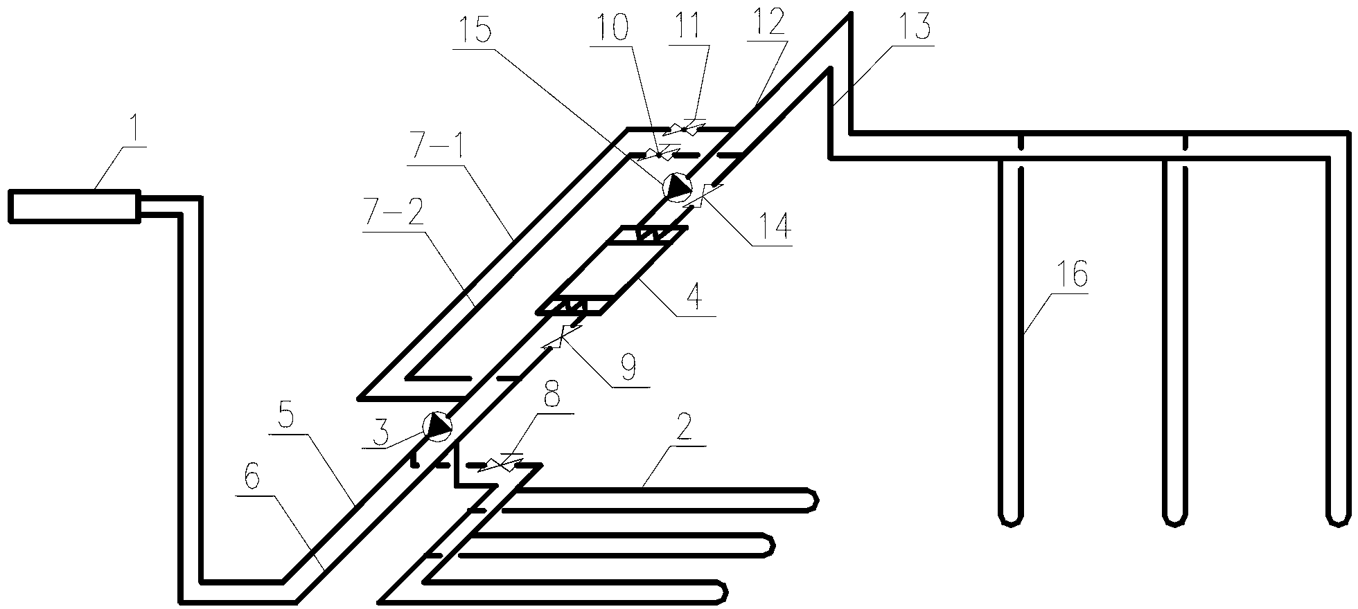
[0012] Specific Embodiment 1: This embodiment is described with reference to FIG. 1. The device in this embodiment includes a fan coil unit 1, a second circulation pump 3, a heat pump unit 4, a high temperature side water supply pipe 5, a high temperature side return water pipe 6, a first Bypass pipe 7-1, second bypass pipe 7-2, first valve 9, second solenoid valve 10, third solenoid valve 11, low temperature side water supply pipe 12, low temperature side return water pipe 13, second valve 14, The first circulating pump 15 and the vertical U-shaped buried pipe heat exchanger 16, the outlet end of the vertical U-shaped buried pipe heat exchanger 16 communicates with the inlet end of the low-temperature side water supply pipe 12, and the outlet ends of the low-temperature side water supply pipe 12 are respectively One end of the first bypass pipe 7-1 communicates with the inlet end of the first circulation pump 15, and the other end of the first bypass pipe 7-1 communicates with...

specific Embodiment approach 2

[0017] Specific embodiment two: this embodiment is described in conjunction with Fig. 1, and the device of this embodiment also includes a horizontal buried heating pipe 2 and a first electromagnetic valve 8, and the inlet end of the horizontal buried heating pipe 2 communicates with the high temperature side water supply pipe 5, The outlet end of the horizontal buried heating pipe 2 communicates with the return pipe 6 on the high temperature side, and the inlet part of the horizontal buried heating pipe 2 is provided with a first electromagnetic valve 8, when the temperature of the soil reference point at the root of the ground plant in the greenhouse or greenhouse is lower than its limit temperature, the first electromagnetic valve 8 is opened, and the heat medium heats the surface layer soil through the horizontal buried heating pipe 2, and when the temperature of the soil layer reaches the set temperature value, the electromagnetic valve 8 is closed. The heat pump unit 4 ca...


PUM


Abstract

The invention discloses an air energy soil-thermal storage heating and cooling device for fruit and vegetable plastic sheds or greenhouses in cold areas, and particularly relates to an air energy soil-thermal storage heating and cooling device which solves the problems of current heating energy waste of winter plastic sheds in the cold areas, failure in cooling in summer, high maintenance cost and disadvantages in planting. Vertical U-shaped ground heat exchangers are respectively communicated with a first by-pass pipe and a first circulating pump through communication of a low-temperature side water supply pipe, and the first by-pass pipe is communicated with a second circulating pump; the first circulating pump is communicated with a heat pump unit which is communicated with a low-temperature side return water pipe; the heat pump unit is communicated with the second circulating pump which is communicated with a fan coil; the fan coil is respectively communicated with a second by-pass pipe and a first valve, the second by-pass pipe is communicated with the low-temperature side return water pipe, and the first valve is communicated with the heat pump unit; and the low-temperature side return water pipe is communicated with the vertical U-shaped ground heat exchangers.

Description

technical field [0001] The invention relates to an air energy soil heat storage heating and cooling device. Background technique [0002] In cold regions, the outdoor temperature is low in winter, and the temperature in greenhouses or greenhouses (hereinafter referred to as "greenhouses") for growing fruits, vegetables and flowers is also generally low. Generally, by the end of November, if there is no heating in the shed, the plants will no longer be able to grow normally. In order for the plants to grow normally, heating must be carried out until late February or early March of the following year. After May in summer, if there is no cooling, the temperature inside the shed will be too high due to the high intensity of solar radiation, the shed must be opened for natural ventilation, and plants can only grow in a natural environment. [0003] At present, there are mainly the following methods for heating greenhouses in winter in cold regions. One is to use small coal sto...

Claims


Application Information

Patent Timeline
Patent Type & Authority Applications(China)
IPC IPC(8): A01G9/24
CPCY02A40/25Y02P60/14
Inventor 郑茂余齐杰郑超
Owner HARBIN INST OF TECH
Why Eureka
Try Eureka