A heat source supply method and device for scr denitrification reducing agent urea pyrolysis

A technology of reducing agent and urea is applied in the field of preparation of reducing agent for flue gas denitration, which can solve the problems of high energy consumption and high operating cost in urea pyrolysis, and achieve the effects of small impact, saving operating cost, reducing energy consumption and plant electricity consumption.

Active Publication Date: 2015-11-18
DONGFANG BOILER GROUP OF DONGFANG ELECTRIC CORP
View PDF5 Cites 3 Cited by
  • Summary
  • Abstract
  • Description
  • Claims
  • Application Information

AI Technical Summary

Problems solved by technology

At present, the heat source of urea pyrolysis mainly adopts the primary air heated by the boiler and is equipped with an electric heater or a gas heater. For example, for the flue gas denitrification device of a 600MW unit, the energy consumption of the urea pyrolysis process using electric heating is: 500kW / h- 1800kW / h, urea pyrolysis consumes a lot of energy and high operating costs

Method used


Image

  • A heat source supply method and device for scr denitrification reducing agent urea pyrolysis

Examples


Embodiment Construction

[0025] The following non-limiting examples illustrate the invention.

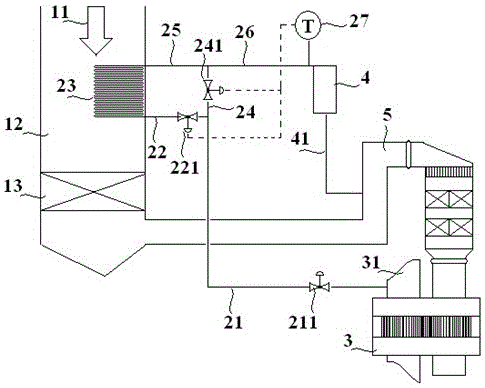
[0026] like figure 1 As shown, the urea pyrolysis air pipeline 21 leads the hot primary air 31 of the air preheater 3 (accounting for 0.5-5% of the total air volume, temperature 0-400°C, pressure 10±5kPa), and passes through the air-tracheal heat exchanger The inlet pipe 22 enters the gas-gas tube heat exchanger 23, and is heated by the boiler flue gas 11, and the air in the gas-gas tube heat exchanger 23 is heated to a temperature equivalent to the temperature of the flue gas, meeting the urea pyrolysis temperature of 400°C-900°C . The heated air enters the urea pyrolysis reactor 4 through the outlet pipe 25 of the gas-air pipe heat exchanger and the inlet pipe 26 of the urea pyrolysis reactor. In the urea pyrolysis reactor 4, the urea solution is pyrolyzed to generate ammonia gas mixture , the ammonia gas mixture enters the denitration reaction device 5 through the urea solution pyrolysis product pipeli...


PUM


Abstract

The invention discloses SCR (Selective Catalytic Reduction) denitration reducing agent urea pyrolysis heat source supply method and device, belonging to the field of preparing an NOx denitration reducing agent. The method comprises the steps of arranging a heat exchanger at a boiler flue gas area, and heating primary hot air which is introduced into the heat exchanger to the pyrolysis temperature of urea by utilizing the boiler flue gas of the area. The device comprises the boiler flue gas area with flue gas temperature of 400-900 DEG C, a device capable of generating primary hot air in the boiler, and an urea pyrolysis reactor, wherein the heat exchanger is arranged at the boiler flue gas area, the heat exchanger is connected with the device capable of generating primary hot air in the boiler, and used for introducing the primary hot air to be heated by flue gas of the boiler flue gas area, and the primary hot air heated by the heat exchanger is introduced to the urea pyrolysis reactor. The invention relates to an SCR denitration reducing agent urea pyrolysis heat source supply method and device which are lower in the energy consumption and running cost of the urea pyrolysis technique.

Description

technical field [0001] The invention belongs to the field of preparation of flue gas denitrification reducing agent. Background technique [0002] Selective catalytic reduction of flue gas denitrification process (SelectiveCatalyticReductionofNOx, referred to as SCR denitrification process) mainly has three kinds of reducing agents: liquid ammonia, ammonia water and urea. Liquid ammonia is widely used in the SCR denitrification process due to its simple process system and low investment and operating costs. However, liquid ammonia is a hazardous chemical with strict requirements for transportation and storage, and its approval is increasingly subject to regulations. It is extremely inconvenient; similarly, ammonia water is also limited in application due to its transportation, storage problems and high investment and operation costs; as a SCR denitrification reducing agent with relatively low safety requirements-urea has the same denitrification performance as liquid ammonia...

Claims


Application Information

Patent Timeline
Patent Type & Authority Patents(China)
IPC IPC(8): B01D53/90B01D53/56F23J15/04
Inventor 杨志忠叶茂宋晓宏黄敏何维
Owner DONGFANG BOILER GROUP OF DONGFANG ELECTRIC CORP
Why Eureka
Try Eureka