
Flywheel inverted pendulum system based on magnetic eddy current effect

An electromagnetic eddy current and inverted pendulum technology, applied in the field of inverted pendulum systems, can solve the problems of small swing angle range and small inverted pendulum torque, and achieve the effect of reducing mass and volume

Active Publication Date: 2015-05-20
BEIJING UNIV OF TECH
View PDF4 Cites 0 Cited by
  • Summary
  • Abstract
  • Description
  • Claims
  • Application Information

AI Technical Summary

Problems solved by technology

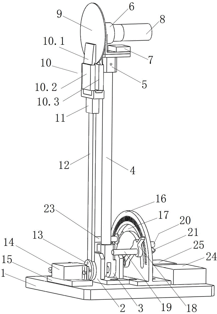
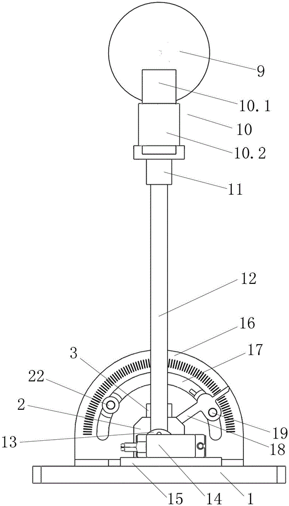
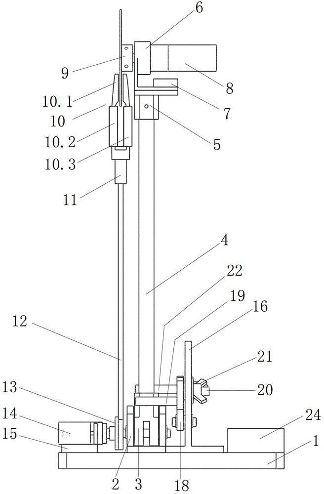
[0005] In order to overcome the problems of the existing flywheel inverted pendulum with small torque and small swing angle range, the present invention provides a flywheel inverted pendulum system based on the electromagnetic eddy current effect, which is produced by rotating and cutting the magnetic force lines in the magnetic field generated by the electromagnet by the metal disc flywheel. Eddy current, the eddy current on the metal disc flywheel produces a reaction magnetic field, which interacts with the magnetic field of the electromagnet to generate torque, and the inverted pendulum where the metal disc flywheel is located swings under the action of this torque, by controlling the rotation of the metal disc flywheel The speed, the excitation current of the electromagnet and the position of the electromagnet can control the torque generated, so as to realize the control of the inverted pendulum

Method used


Image

  • Flywheel inverted pendulum system based on magnetic eddy current effect
  • Flywheel inverted pendulum system based on magnetic eddy current effect
  • Flywheel inverted pendulum system based on magnetic eddy current effect

Examples


Embodiment Construction

[0042] Below in conjunction with embodiment specifically introduces the workflow of the present invention:

[0043] Such as Figure 5 As shown: by tightening the first nut 21, the pointer limit pin 20 can be fixed on the dial 16, so that the scale pointer 18 can be fixed on the corresponding scale of the dial 16, and the swing rod limit pin 19 can be fixed on the scale pointer 18 in the corresponding position. Similarly, when the second nut 23 is tightened, the swing rod independent limit pin 22 is fixed on the dial 16 . The swing rod limit pin 19 and the swing rod independent limit pin 22 are located on both sides of the inverted swing rod 4 respectively, and play a limiting and supporting role on the inverted swing rod 4 . When the control signal was not applied to the inverted pendulum system, the inverted pendulum bar 4 would tilt to the left or right, Figure 6 Take the inverted fork 4 tilted to the right as an example in the middle, and the fork limit pin 19 supports ...


PUM


Abstract

A flywheel inverted pendulum system based on the magnetic eddy current effect comprises a flywheel inverted pendulum mechanism, an electromagnet driving pendulum mechanism and an angulometer limiting mechanism. A metal disc flywheel rotates and cut magnetic eddy current produced by a magnetic force line in a magnetic field produced by an electromagnet, a counter magnetic field produced by the eddy current and the magnetic field produced by the electromagnet play mutual effect to produce force moment, and a pendulum rod of an inverted pendulum swings under the effect of the force moment. The system controls produced force moment by controlling an angular velocity of the flywheel in rotation and exciting current of the electromagnet. By means of the method, the force moment of the flywheel is increased, the effect time of the force moment is prolonged, the mass and the volume of the system are reduced, the control effect is improved, and an application range is widened.

Description

1. Technical field: [0001] The invention relates to an inverted pendulum system, in particular to a flywheel inverted pendulum system based on the electromagnetic eddy current effect 2. Background technology: [0002] The inverted pendulum system is a non-minimum phase, multi-variable, absolutely unstable nonlinear system, so the inverted pendulum control system is a typical example of the application of control theory, and its control methods are widely used in aerospace and robotics. The application number is 201010151221.0, and the patent application titled "A Flywheel-Based Inverted Pendulum Balance Control System" discloses an inverted pendulum system that utilizes the flywheel rotation to generate torque to control the balance of the inverted pendulum. The inverted pendulum system adopts a rotating flywheel with a certain mass on the top of the inverted pendulum, and the inverted pendulum is deflected by the counter torque generated by the rotation of the flywheel. ...

Claims


Application Information

Patent Timeline
Patent Type & Authority Patents(China)
IPC IPC(8): B25J13/00
Inventor 阮晓钢孙荣毅朱晓庆左国玉于乃功于建均
Owner BEIJING UNIV OF TECH
Learn More