Master nozzle structure of jet-type textile machine and mounting method thereof

A technology for main nozzles and textile machines, applied in textiles, looms, textiles and papermaking, etc., can solve the problems of high production costs, affecting production progress, high energy consumption, etc., and achieve the goals of reducing jet flow rate, improving production efficiency and reducing costs Effect

Active Publication Date: 2013-07-10
苏州通捷纺织有限公司
View PDF11 Cites 11 Cited by
  • Summary
  • Abstract
  • Description
  • Claims
  • Application Information

AI Technical Summary

Problems solved by technology

This not only causes waste of labor costs and raw material costs to a certain extent, but also affects the production progress and low production efficiency.
At the same time, since the air-jet loom adopts the air-flow weft insertion method, the biggest disadvantage is that the energy consumption is high and the production cost is high.

Method used


Image

  • Master nozzle structure of jet-type textile machine and mounting method thereof
  • Master nozzle structure of jet-type textile machine and mounting method thereof
  • Master nozzle structure of jet-type textile machine and mounting method thereof

Examples


Embodiment Construction

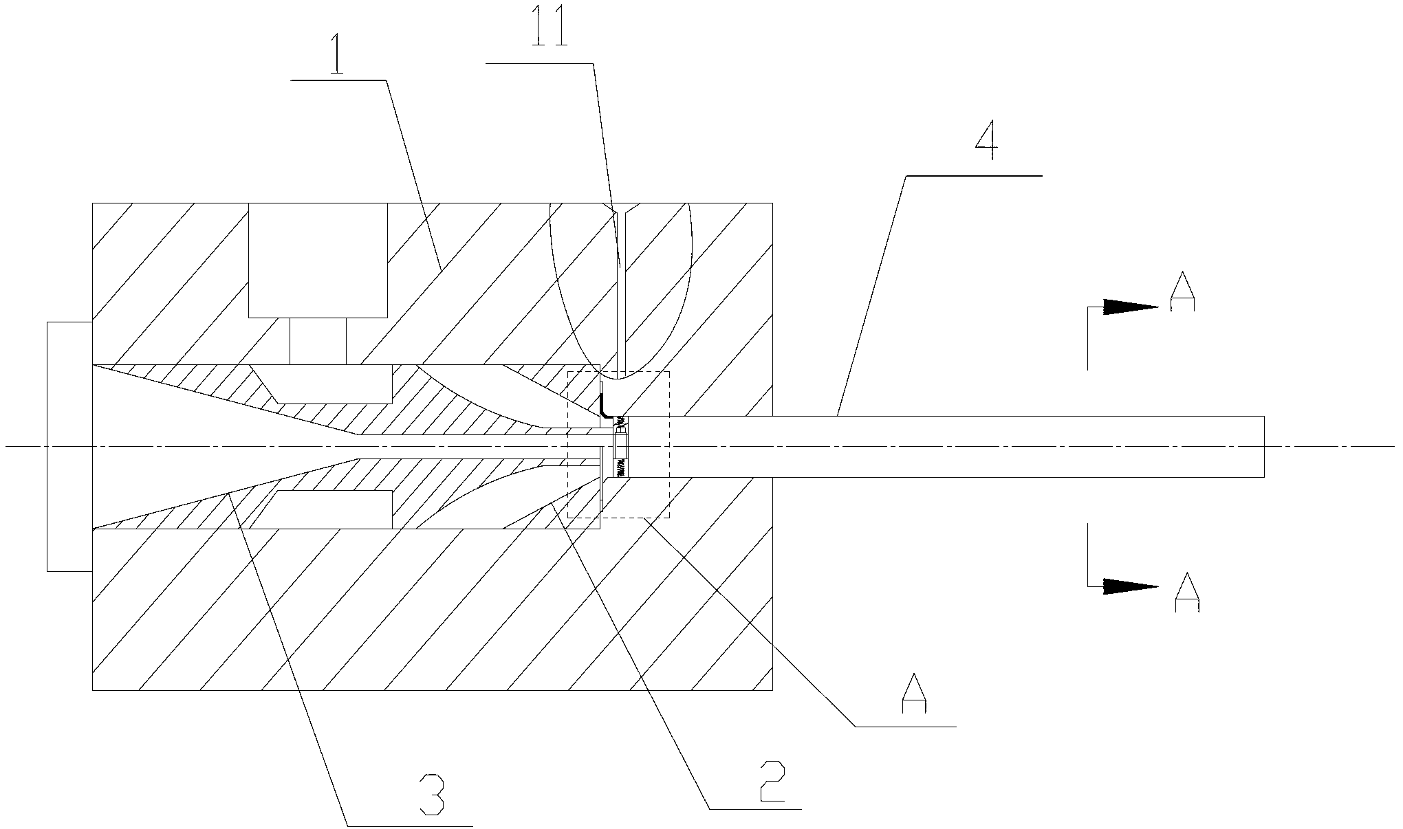
[0040] During the weaving process, since different types of yarns need to be replaced with corresponding main nozzles, this not only causes waste of labor costs and raw material costs to a certain extent, but also affects production progress and low production efficiency. At the same time, because the air-jet loom adopts the air-flow weft insertion method, there are problems and deficiencies such as high energy consumption and high production cost.

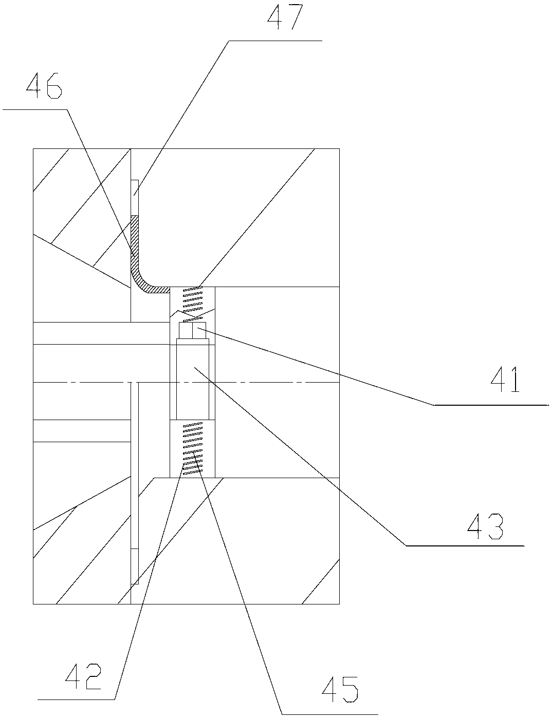
[0041] The present invention aims at the deficiencies in the prior art. The present invention provides a main nozzle structure and assembly method of an air-jet textile machine, so that the main nozzle can adjust the throat gap of the main nozzle according to the different yarn types to meet the needs of textile production. Need, reduce the cost of labor and raw materials, improve production efficiency, and at the same time can adjust and optimize the jet flow rate to save energy consumption.

[0042] The technical solutions of th...


PUM


Abstract

The invention discloses a master nozzle structure of a jet-type textile machine. The master nozzle structure comprises a nozzle body, a tapered sleeve, a nozzle core and a yarn guiding tube which are arranged inside the nozzle body. The yarn guiding tube comprises a fixedly-connected fixing end and an adjusting end. The yarn guiding tube are formed by two segments, so that the size of the fixing end is processed and manufactured according to the largest diameter of a jet-type textile machine; and the diameter of the adjusting end can be adjusted by rotating a driving screw according to different types of the yarn, so that the size of a gap at the throat portion of the master nozzle is adjusted to meet the requirements of textile production. The process step of turning down the machine to change the master nozzle in working can be omitted, labor and raw materials are reduced, working efficiency is improved; and meanwhile, when yarns with small twist are adopted, air flow rate is constant, and the gap of the master nozzle can be accordingly increased by reducing the diameter of the adjustable end, so that jet flow speed is reduced, and energy is saved.

Description

technical field [0001] The invention belongs to the technical field of textile machinery, and in particular relates to a main nozzle structure and an assembly method of an air-jet textile machine. Background technique [0002] The air-jet loom is a shuttleless loom that uses jet air to pull the weft through the shed. Since the Americans invented the air-jet loom in 1914 and the first commercial air-jet loom was produced in Czechoslovakia in 1950, the air-jet loom began to be used in industrial production in the 1970s. Its working principle is to use air as the weft insertion medium, and use the compressed air jet to generate friction and traction on the weft yarn to pull the weft yarn through the shed, and achieve the purpose of weft insertion through the jet generated by the air jet. [0003] This weft insertion method enables the loom to achieve high speed and high production. Among several shuttleless looms, the air-jet loom is the one with the highest speed. Due to the...

Claims


Application Information

Patent Timeline
Patent Type & Authority Applications(China)
IPC IPC(8): D03D47/30D03D49/26
Inventor 冯志华刘帅
Owner 苏州通捷纺织有限公司
Why Eureka
Try Eureka