Method for buffering reciprocating impact tunneling counter-acting force and buffering heading machine adopting the method

A technology of reaction force and roadheader, which is applied in the direction of cutting machinery, earth drilling and cutting machinery, etc., and can solve the problems of cutting power unit and machine body damage, etc.

Active Publication Date: 2013-07-10
刘素华
View PDF5 Cites 16 Cited by
  • Summary
  • Abstract
  • Description
  • Claims
  • Application Information

AI Technical Summary

Problems solved by technology

Its defect is: the reaction force of the excavator to the fuselage is stronger during the reciprocating impact, and the damage to the cutting power unit and the fuselage is serious

Method used


Image

  • Method for buffering reciprocating impact tunneling counter-acting force and buffering heading machine adopting the method
  • Method for buffering reciprocating impact tunneling counter-acting force and buffering heading machine adopting the method
  • Method for buffering reciprocating impact tunneling counter-acting force and buffering heading machine adopting the method

Examples


Embodiment 1

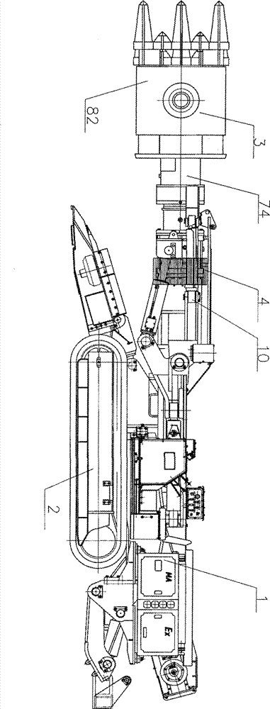
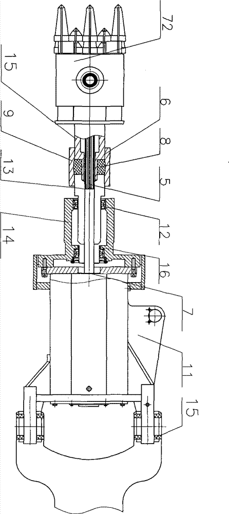
[0097] Figure 1 to Figure 3 It is a buffer roadheader for buffering the reaction force of reciprocating impact excavation described in Example 1, including a fuselage 1 , a running part 2 , a reciprocating impact part 3 , and a buffer device 4 . The buffer device 4 includes a power buffer device 5 and a structural buffer guide device 6. The power buffer device 5 includes a rotating power buffer device 7. The structural buffer guide device 6 includes a structural buffer device 8 and a buffer guide device 9. The reciprocating impact part includes an impact drive device 10. , the impact driving device 10 includes a rotary power source part 11, a rotary impact transmission part 12, a rotary power buffer device 7 is arranged between the rotary power source part 11 and the rotary impact transmission part 12, and the rotary power buffer device 7 includes a sliding travel spline shaft Cover the buffer device 13, the reciprocating impact part 3 also includes a fixed support 14 and a b...

Embodiment 2

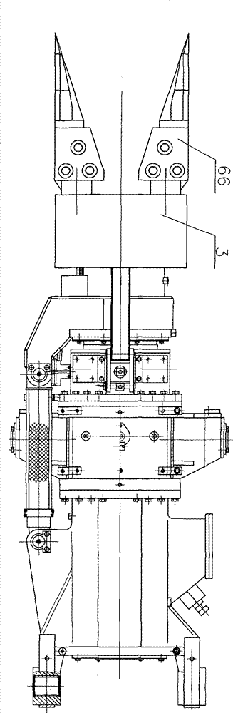
[0102] Figure 4 It is the buffer boring machine described in embodiment 2. Different from Embodiment 1, the rotating power buffer device 7 includes a belt buffer device 17, and the belt buffer device 17 includes a driving pulley 18, a belt 19, and a driven pulley 20, and the driving pulley 18 is fixed on the fixed support 14, and the rotating power source The part is a motor 21, the driving pulley 18 is connected with the drive shaft 22 or the drive sleeve of the motor 21, the driven pulley 20 is arranged on the buffer support member 15, the belt 19 is arranged on the driving pulley 18 and the driven pulley 20, and the driven pulley 20 As the buffer support member 15 is subjected to impact movement, the belt 19 absorbs the impact reaction force to form a belt buffer device 17, and the belt buffer device 17 prevents the motor 21 from being damaged.

[0103] The rotary power source 11 may also be a hydraulic motor or an air motor.

[0104] Others are with embodiment 1.

Embodiment 3

[0106] Figure 5 , 6 It is the buffer boring machine described in embodiment 3. What is different from Embodiment 1 is that the belt buffer device 17 includes a driving pulley 18, a belt 19, and a driven pulley 20, the driving pulley 18 is fixed on the fixed support 14, the rotating power source 11 is a motor 21, and the driving pulley 18 and the motor 21 of the drive shaft 22 or drive sleeve connection, the driven pulley 20 is arranged on the buffer support 15, the belt 19 is arranged on the driving pulley 18 and the driven pulley 20, and the driven pulley 20 is impacted with the buffer support 15. , The belt 19 absorbs the impact reaction force to form a belt buffer device 17, and the belt buffer device 17 prevents the motor 21 from being damaged. Belt buffer device 17 also comprises tensioner 23, and tensioner 23 comprises connecting arm 24, bearing 25, return spring 26, positioning pin 27 etc., connecting arm 24, return spring 26 and bearing 25 are hinged by hinge , Can...


PUM


Abstract

The invention belongs to the field of digging and relates to a method for buffering a reciprocating impact tunneling counter-acting force and a buffering heading machine adopting the method. The buffering heading machine comprises a machine body, a travel unit, a reciprocating impact unit, and a buffering unit. The buffering unit comprises a dynamic buffering device or a structure buffering guiding device. The reciprocating impact unit comprises an impact driving device, a fixing support and a buffering support. The dynamic buffering device comprises a rotary dynamic buffering device. The rotary dynamic buffering device comprises a slide stroke splined hub buffering device or a belt buffering device. The structure buffering guiding device is arranged between the reciprocating impact unit and the machine body or between the fixing support and the buffering support. The structure buffering guiding device can guide a buffering direction of the dynamic buffering device and/or a structure buffering device. The buffering unit can buffer and resolve a counter-acting force on the reciprocating impact unit. The reciprocating impact unit is arranged at the machine body. The travel unit drives the machine body to travel.

Description

technical field [0001] The invention relates to tunneling equipment, in particular to a method for buffering the reaction force of reciprocating impact tunneling and a buffer tunneling machine implementing the method. Background technique [0002] The currently widely used mining excavation equipment is the cantilever type roadheader. Its working principle is drilling type; at present, numerous percussion type roadheaders have been developed in succession in this field. Both excavation methods have relatively large reaction force on the fuselage, which is easy to cause damage to the fuselage during the excavation process. [0003] The patent No. is 200620137402.7, and the name is called "energy-saving impact mining machine" and discloses a mining machine with an impact arm and an impact head. The output shaft of the motor is connected with the variable speed transmission mechanism. When the motor is working, the variable speed transmission mechanism converts the rotational...

Claims


Application Information

Patent Timeline
Patent Type & Authority Applications(China)
IPC IPC(8): E21C25/02E21C31/02E21C35/04
Inventor 刘素华
Owner 刘素华
Why Eureka
Try Eureka