Turbine cooling system

A technology for cooling systems and turbines, applied in mechanical equipment, engine components, machines/engines, etc., to solve problems such as the overall performance reduction of turbines

Inactive Publication Date: 2013-07-10
GENERAL ELECTRIC CO
View PDF6 Cites 3 Cited by
  • Summary
  • Abstract
  • Description
  • Claims
  • Application Information

AI Technical Summary

Problems solved by technology

Thus, the orifices also lead to a reduction in the overall performance of the turbine by supplying more cooling air than necessary at less operating conditions than necessary

Method used


Image

  • Turbine cooling system
  • Turbine cooling system

Examples


Embodiment Construction

[0018] As used in this specification, the terms module and submodule refer to an Application Specific Integrated Circuit (ASIC), an electronic circuit, a processor (shared, dedicated or grouped) and memory, a combination of Logic circuits and / or other suitable components that provide the described functionality.

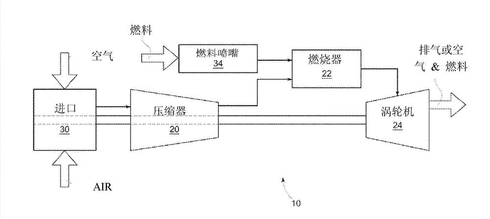
[0019] figure 1 A schematic diagram of an exemplary power generation system indicated by reference numeral 10 is shown. Power generation system 10 is a gas turbine system having compressor 20 , combustor 22 and turbine 24 . Air enters power generation system 10 through an air inlet 30 located in compressor 20 and is compressed by compressor 20 . The compressed air is then mixed with fuel through fuel nozzles 34 located in the end cover (not shown) of the combustor 22 . Fuel nozzles 34 inject an air-fuel mixture into combustor 22 at a ratio for combustion. Combustion produces hot, pressurized exhaust gas that drives blades (not shown) located within turbine 24 . ...


PUM


Abstract

A turbine cooling system is provided, having a compressor for supplying cooling air, a forward turbine rotor wheel space, a high-pressure packing seal (HPPS) bypass cavity, and a metering device. The forward turbine rotor wheel space is cooled by the cooling air supplied by the compressor. The HPPS bypass cavity is in fluid communication with and receives a portion of the cooling air from the compressor, and is in fluid communication with and supplies the cooling air to the forward turbine rotor wheel space. The metering device is in operable communication with the forward turbine rotor wheel space and the HPPS bypass cavity to modulate the cooling air supplied to the forward turbine rotor wheel space from the HPPS bypass cavity. The metering device modulates the cooling air based on at least one operating condition of the turbine.

Description

technical field [0001] The presently disclosed subject matter relates to turbine cooling systems, and more particularly to cooling systems having a metering device for regulating cooling air supplied to a forward turbine rotor wheel space. Background technique [0002] A gas turbine generally includes a compressor, a combustor, one or more fuel nozzles, and a turbine. Air enters the gas turbine through the intake and is pressurized by the compressor. The pressurized air is then mixed with fuel supplied through the fuel nozzles. The air-fuel mixture is supplied to the combustors in a specific ratio for combustion. Combustion produces pressurized exhaust gases that drive the blades of the turbine. [0003] The turbine includes a rotor assembly having a plurality of turbine blades mounted on a rotating disk. During operation, turbine blades, rotating disks, and other components in a turbine are exposed to high temperatures. In order to maintain the temperature of the inter...

Claims


Application Information

Patent Timeline
Patent Type & Authority Applications(China)
IPC IPC(8): F01D5/18
CPCF01D5/081F01D5/082F01D5/087F01D11/001F01D25/08F01D25/12
Inventor J.N.库克
Owner GENERAL ELECTRIC CO
Why Eureka
Try Eureka