Engine exhaust manifold assembly
An exhaust manifold and engine technology, applied in engine components, machines/engines, exhaust devices, etc., can solve the problems of low exhaust gas temperature, failure to meet emission standards, failure to meet emission requirements, etc. The effect of low pressure, good engine power and uniform exhaust gas mixing
- Summary
- Abstract
- Description
- Claims
- Application Information
AI Technical Summary
Problems solved by technology
Method used
Image
Examples
Embodiment Construction
[0017] The present invention will be further described below in conjunction with drawings and embodiments.
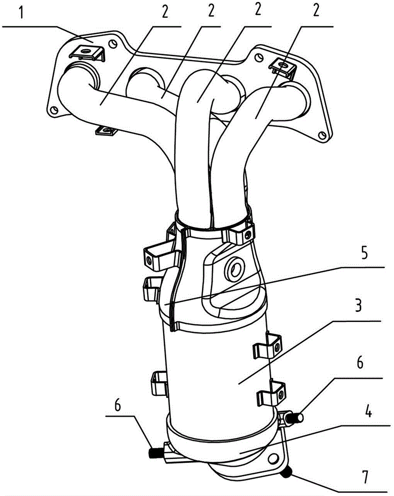
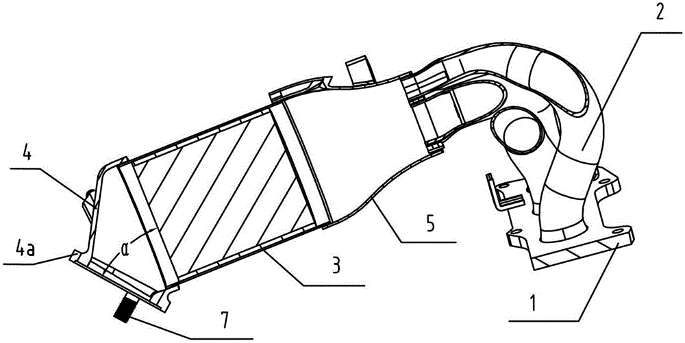
[0018] Such as figure 1 , figure 2 The engine exhaust manifold assembly shown is composed of intake flange 1, multiple exhaust manifolds 2 arranged side by side, three-way catalytic converter 3, outlet flange 4, horn-shaped transition pipe 5, support screws 6 and Connecting screw 7 forms.
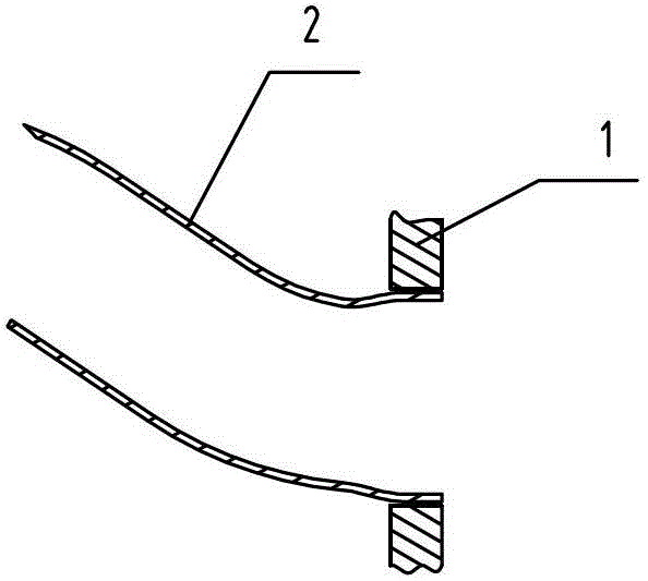
[0019] to combine image 3 As shown, each exhaust manifold 2 is made of bent stainless steel pipes with basically the same length. The three-way catalytic converter 3 is cylindrical. After the rear ends of the exhaust manifolds 2 are brought together, they are connected to the front end of the three-way catalytic converter 3 through a horn-shaped transition pipe 5. The inner diameter of the horn-shaped transition pipe 5 is determined by the front end It gradually increases toward the rear end, that is, the exhaust gas is first compressed in the horn-shaped transition pipe 5 and ...
PUM
 Abstract
Description
Claims
Application Information
 - R&D
- Intellectual Property
- Life Sciences
- Materials
- Tech Scout
- Unparalleled Data Quality
- Higher Quality Content
- 60% Fewer Hallucinations
Browse by: Latest US Patents, China's latest patents, Technical Efficacy Thesaurus, Application Domain, Technology Topic, Popular Technical Reports.
© 2025 PatSnap. All rights reserved.Legal|Privacy policy|Modern Slavery Act Transparency Statement|Sitemap|About US| Contact US: help@patsnap.com


