A ceramic cone valve

A technology of cone valve and ceramic valve core, which is applied in the direction of valve device, cock including cut-off device, engine components, etc. It can solve the problems of short service life of metal cone valve, wear gap between valve core and middle body, high cost of use, etc. , to achieve the effects of good sealing performance, smooth switching and low cost of use

Inactive Publication Date: 2016-01-13
烟台明珠陶瓷科技有限公司
View PDF9 Cites 0 Cited by
  • Summary
  • Abstract
  • Description
  • Claims
  • Application Information

AI Technical Summary

Problems solved by technology

[0002] Cone valves have the advantages of high temperature resistance, corrosion resistance, wear resistance, erosion resistance, etc., and are widely used in various acid-base salt gases, liquids, high-temperature steam in chemical industry, metallurgy, papermaking, electric power, medicine, environmental protection and other industries And the slurry conveying system, after a long time of use, the ordinary metal cone valve will wear and tear between the valve core and the middle body to form a gap and cause leakage, so it can only be scrapped, so the metal cone valve has short service life and high cost of use. high problem

Method used


Image

  • A ceramic cone valve
  • A ceramic cone valve
  • A ceramic cone valve

Examples


Embodiment 1

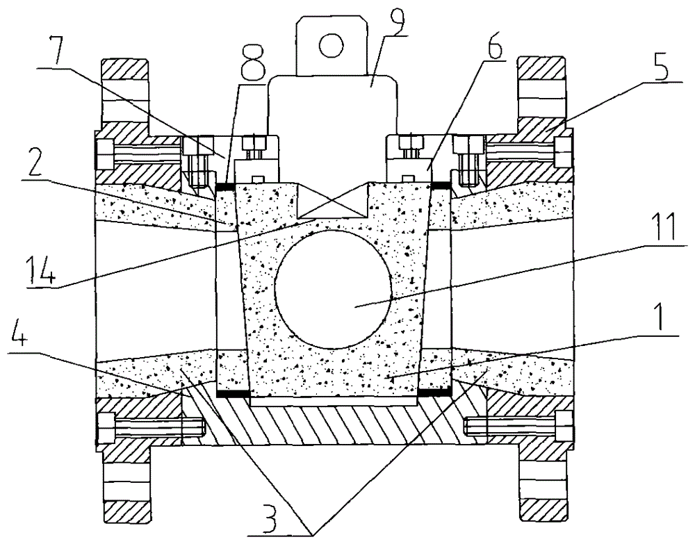
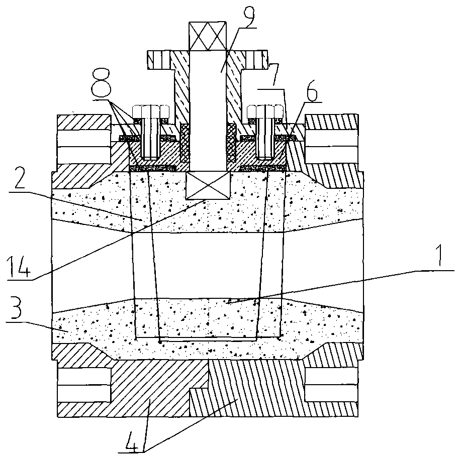
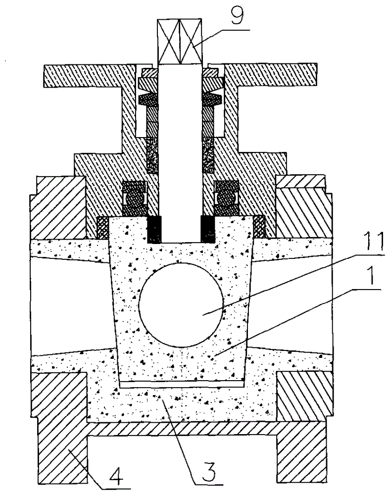
[0042] The ceramic cone valve of the present embodiment, refer to figure 1 , Figure 11-14 , including a shell 4, the shell 4 is a metal shell, the shell 4 is a split structure, the shell 4 is screwed to the flange 5, the shell 4 is provided with a middle body 2, and the middle body 2 is made of ceramics, The inner body 2 is tightly fitted with a ceramic valve core 1. The ceramic valve core 1 is in an upper conical shape with a thick top and a thin bottom. The taper of the ceramic valve core 1 is 4 degrees. The outer periphery of the middle body 2 is provided with a ceramic flange lining 3. The top of the ceramic valve core 1 is provided with an adjustment pressure ring 6, and the top of the adjustment pressure ring 6 is connected with an adjustment pressure plate 7, and the adjustment pressure plate 7 is threadedly connected with the housing 4. A stem hole 14 is provided at the top, and a through hole 11 is provided in the middle of the ceramic valve core 1, and the through ...

Embodiment 2

[0044] The ceramic cone valve of the present embodiment, refer to Figure 2-A , Figure 2-B , Figure 9 , Figure 10 , Figure 13 , Figure 15 , including a shell 4, the shell 4 is welded or screwed together by two metal shells occluded, the shell 4 is provided with a middle body 2, the middle body 2 is made of ceramics, and the middle body 2 is closely fitted with a sleeve There is a ceramic spool 1, the ceramic spool 1 is an upper conical shape with a thick top and a thin bottom, the taper of the ceramic spool 1 is 4 degrees, the outer periphery of the middle body 2 is provided with a ceramic flange lining 3, and the top of the ceramic spool 1 is set There is an adjustment pressure ring 6, and an adjustment pressure plate 7 is connected above the adjustment pressure ring 6, and the adjustment pressure plate 7 is threadedly connected with the housing 4, and the valve stem 9 is installed on the ceramic valve core 1, and the outer circumference of the valve stem 9 is sealed...

Embodiment 3

[0046] The ceramic cone valve of the present embodiment, refer to Figure 2-C , Figure 2-D , Figure 11 , Figure 12 , Figure 13 , Figure 16 , including a shell 4, the shell 4 is a metal shell, the shell 4 is a split structure, the shell 4 is screwed to the flange pressure ring 10, the shell 4 is provided with a middle body 2, and the middle body 2 is made of ceramics The middle body 2 is tightly fitted with a ceramic valve core 1. The ceramic valve core 1 is in the shape of an upper cone with a thick top and a thin bottom. The taper of the ceramic valve core 1 is 4 degrees. The outer periphery of the middle body 2 is provided with a ceramic flange lining. 3. There is a step 12 on the ceramic flange lining 3, an adjustment pressure ring 6 is provided above the ceramic valve core 1, and an adjustment pressure plate 7 is connected above the adjustment pressure ring 6, and the adjustment pressure plate 7 is threadedly connected with the housing 4, and the ceramic A valve ...


PUM


Abstract

The invention relates to a rotary cone valve, in particular relates to a ceramic rotary cone valve, and belongs to the technical field of rotary cone valves. The ceramic rotary cone valve comprises a shell, wherein the shell is a metal shell or a ceramic shell, has a split structure or an integrated structure, and is in threaded connection with a flange or a flange pressing ring; an intermediate is arranged in the shell and is made of ceramics or polytetrafluoroethylene; and a ceramic valve core is sleeved in the intermediate in a close fit manner. According to the ceramic rotary cone valve, a clearance between the ceramic valve core and the intermediate can be adjusted, so that an optimal sealing effect is achieved; a ceramic flange liner is in close fit with the flange pressing ring through an additionally arranged step, so that the problem that the ceramic flange liner easily drops off at high temperature in the prior art is solved; the intermediate can be made of a polytetrafluoroethylene material, so that the ceramic rotary cone valve is high in sealing performance, cannot be scratched, is small in torque, and is smoothly turned on and turned off; and with the structure, the ceramic rotary cone valve is long in service life and low in using cost.

Description

technical field [0001] The invention relates to a cone valve, in particular to a ceramic cone valve, which belongs to the technical field of cone valves. Background technique [0002] Cone valves have the advantages of high temperature resistance, corrosion resistance, wear resistance, erosion resistance, etc., and are widely used in various acid-base salt gases, liquids, high-temperature steam in chemical industry, metallurgy, papermaking, electric power, medicine, environmental protection and other industries And the slurry conveying system, after a long time of use, the ordinary metal cone valve will wear and tear between the valve core and the middle body to form a gap and cause leakage, so it can only be scrapped, so the metal cone valve has short service life and high cost of use. high question. Contents of the invention [0003] The purpose of the present invention is to solve the shortcomings of the above-mentioned prior art, and provide a ceramic spiral cone valv...

Claims


Application Information

Patent Timeline
Patent Type & Authority Patents(China)
IPC IPC(8): F16K5/02F16K5/08
Inventor 步志俊
Owner 烟台明珠陶瓷科技有限公司
Why Eureka
Try Eureka